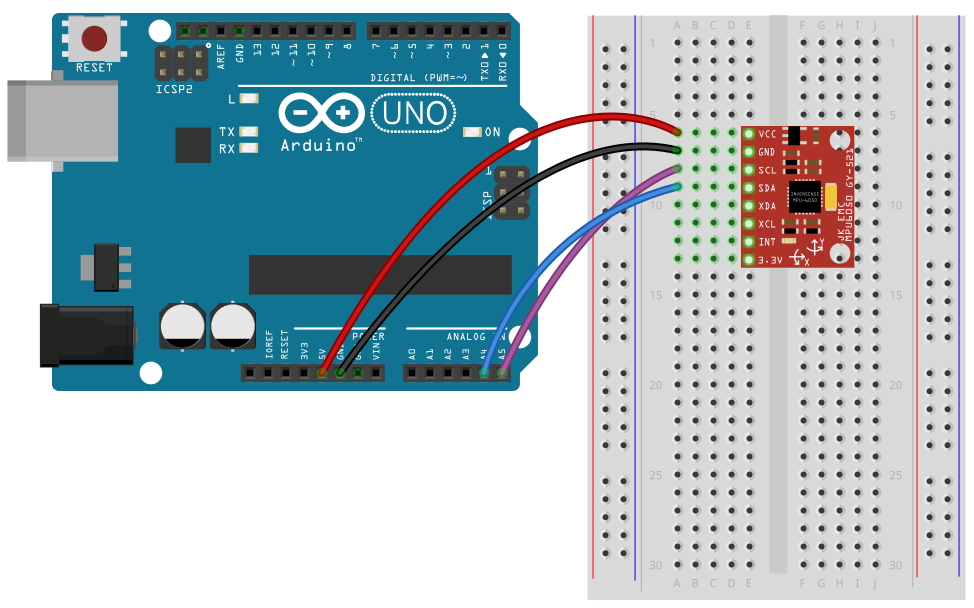
(1) 아두이노 UNO R3와 연결해서 가속도, 자이로 센터 데이터 출력 하기
이번 예제에서는 인터럽트를 사용하지 않기 때문에 INT핀을 연결할
필요는 없다. 본
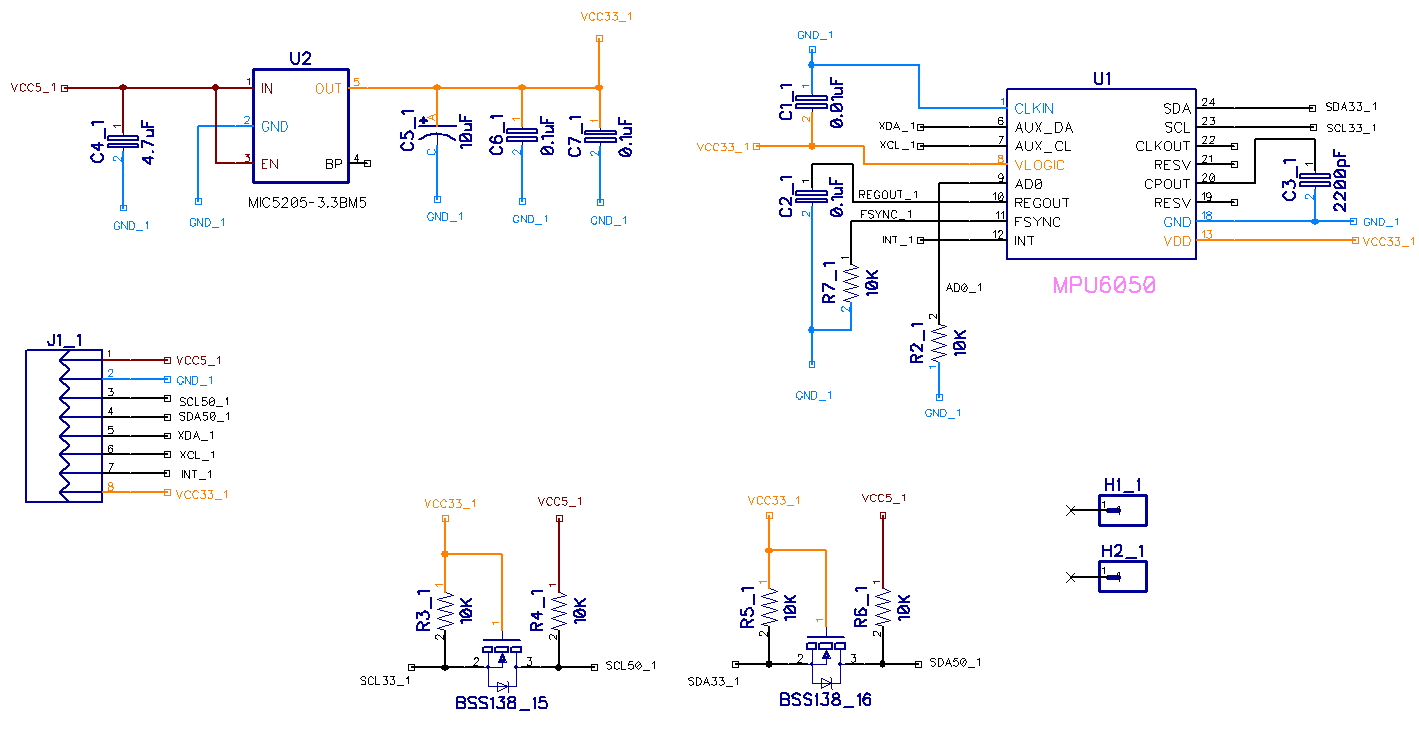
제품은 내부에 회로적으로 3.3V전원 레듈레이터와 I2C 레벨쉬프터를 내장하고 있어서 5.0V와 3.3V 에서 모두 사용이 가능
하다. STM32, 라즈베리파이 등과 같이 3.3V 전원을 사용하는 프로세서에서 사용할 경우에는 VCC 대신에 3.3V 핀을
통해서 전원을 바로 연결해 주면 된다.
// MPU-6050 Accelerometer + Gyro // ----------------------------- // // By arduino.cc user "Krodal". // // June 2012 // first version // July 2013 // The 'int' in the union for the x,y,z // changed into int16_t to be compatible // with Arduino Due. // // Open Source / Public Domain // // Using Arduino 1.0.1 // It will not work with an older version, // since Wire.endTransmission() uses a parameter // to hold or release the I2C bus. // // Documentation: // - The InvenSense documents: // - "MPU-6000 and MPU-6050 Product Specification", // PS-MPU-6000A.pdf // - "MPU-6000 and MPU-6050 Register Map and Descriptions", // RM-MPU-6000A.pdf or RS-MPU-6000A.pdf // - "MPU-6000/MPU-6050 9-Axis Evaluation Board User Guide" // AN-MPU-6000EVB.p // // The accuracy is 16-bits. // // Temperature sensor from -40 to +85 degrees Celsius // 340 per degrees, -512 at 35 degrees. // // At power-up, all registers are zero, except these two: // Register 0x6B (PWR_MGMT_2) = 0x40 (I read zero). // Register 0x75 (WHO_AM_I) = 0x68. //
#include <Wire.h>
// The name of the sensor is "MPU-6050". // For program code, I omit the '-', // therefor I use the name "MPU6050....".
// Register names according to the datasheet. // According to the InvenSense document // "MPU-6000 and MPU-6050 Register Map // and Descriptions Revision 3.2", there are no registers // at 0x02 ... 0x18, but according other information // the registers in that unknown area are for gain // and offsets. // #define MPU6050_AUX_VDDIO 0x01 // R/W #define MPU6050_SMPLRT_DIV 0x19 // R/W #define MPU6050_CONFIG 0x1A // R/W #define MPU6050_GYRO_CONFIG 0x1B // R/W #define MPU6050_ACCEL_CONFIG 0x1C // R/W #define MPU6050_FF_THR 0x1D // R/W #define MPU6050_FF_DUR 0x1E // R/W #define MPU6050_MOT_THR 0x1F // R/W #define MPU6050_MOT_DUR 0x20 // R/W #define MPU6050_ZRMOT_THR 0x21 // R/W #define MPU6050_ZRMOT_DUR 0x22 // R/W #define MPU6050_FIFO_EN 0x23 // R/W #define MPU6050_I2C_MST_CTRL 0x24 // R/W #define MPU6050_I2C_SLV0_ADDR 0x25 // R/W #define MPU6050_I2C_SLV0_REG 0x26 // R/W #define MPU6050_I2C_SLV0_CTRL 0x27 // R/W #define MPU6050_I2C_SLV1_ADDR 0x28 // R/W #define MPU6050_I2C_SLV1_REG 0x29 // R/W #define MPU6050_I2C_SLV1_CTRL 0x2A // R/W #define MPU6050_I2C_SLV2_ADDR 0x2B // R/W #define MPU6050_I2C_SLV2_REG 0x2C // R/W #define MPU6050_I2C_SLV2_CTRL 0x2D // R/W #define MPU6050_I2C_SLV3_ADDR 0x2E // R/W #define MPU6050_I2C_SLV3_REG 0x2F // R/W #define MPU6050_I2C_SLV3_CTRL 0x30 // R/W #define MPU6050_I2C_SLV4_ADDR 0x31 // R/W #define MPU6050_I2C_SLV4_REG 0x32 // R/W #define MPU6050_I2C_SLV4_DO 0x33 // R/W #define MPU6050_I2C_SLV4_CTRL 0x34 // R/W #define MPU6050_I2C_SLV4_DI 0x35 // R #define MPU6050_I2C_MST_STATUS 0x36 // R #define MPU6050_INT_PIN_CFG 0x37 // R/W #define MPU6050_INT_ENABLE 0x38 // R/W #define MPU6050_INT_STATUS 0x3A // R #define MPU6050_ACCEL_XOUT_H 0x3B // R #define MPU6050_ACCEL_XOUT_L 0x3C // R #define MPU6050_ACCEL_YOUT_H 0x3D // R #define MPU6050_ACCEL_YOUT_L 0x3E // R #define MPU6050_ACCEL_ZOUT_H 0x3F // R #define MPU6050_ACCEL_ZOUT_L 0x40 // R #define MPU6050_TEMP_OUT_H 0x41 // R #define MPU6050_TEMP_OUT_L 0x42 // R #define MPU6050_GYRO_XOUT_H 0x43 // R #define MPU6050_GYRO_XOUT_L 0x44 // R #define MPU6050_GYRO_YOUT_H 0x45 // R #define MPU6050_GYRO_YOUT_L 0x46 // R #define MPU6050_GYRO_ZOUT_H 0x47 // R #define MPU6050_GYRO_ZOUT_L 0x48 // R #define MPU6050_EXT_SENS_DATA_00 0x49 // R #define MPU6050_EXT_SENS_DATA_01 0x4A // R #define MPU6050_EXT_SENS_DATA_02 0x4B // R #define MPU6050_EXT_SENS_DATA_03 0x4C // R #define MPU6050_EXT_SENS_DATA_04 0x4D // R #define MPU6050_EXT_SENS_DATA_05 0x4E // R #define MPU6050_EXT_SENS_DATA_06 0x4F // R #define MPU6050_EXT_SENS_DATA_07 0x50 // R #define MPU6050_EXT_SENS_DATA_08 0x51 // R #define MPU6050_EXT_SENS_DATA_09 0x52 // R #define MPU6050_EXT_SENS_DATA_10 0x53 // R #define MPU6050_EXT_SENS_DATA_11 0x54 // R #define MPU6050_EXT_SENS_DATA_12 0x55 // R #define MPU6050_EXT_SENS_DATA_13 0x56 // R #define MPU6050_EXT_SENS_DATA_14 0x57 // R #define MPU6050_EXT_SENS_DATA_15 0x58 // R #define MPU6050_EXT_SENS_DATA_16 0x59 // R #define MPU6050_EXT_SENS_DATA_17 0x5A // R #define MPU6050_EXT_SENS_DATA_18 0x5B // R #define MPU6050_EXT_SENS_DATA_19 0x5C // R #define MPU6050_EXT_SENS_DATA_20 0x5D // R #define MPU6050_EXT_SENS_DATA_21 0x5E // R #define MPU6050_EXT_SENS_DATA_22 0x5F // R #define MPU6050_EXT_SENS_DATA_23 0x60 // R #define MPU6050_MOT_DETECT_STATUS 0x61 // R #define MPU6050_I2C_SLV0_DO 0x63 // R/W #define MPU6050_I2C_SLV1_DO 0x64 // R/W #define MPU6050_I2C_SLV2_DO 0x65 // R/W #define MPU6050_I2C_SLV3_DO 0x66 // R/W #define MPU6050_I2C_MST_DELAY_CTRL 0x67 // R/W #define MPU6050_SIGNAL_PATH_RESET 0x68 // R/W #define MPU6050_MOT_DETECT_CTRL 0x69 // R/W #define MPU6050_USER_CTRL 0x6A // R/W #define MPU6050_PWR_MGMT_1 0x6B // R/W #define MPU6050_PWR_MGMT_2 0x6C // R/W #define MPU6050_FIFO_COUNTH 0x72 // R/W #define MPU6050_FIFO_COUNTL 0x73 // R/W #define MPU6050_FIFO_R_W 0x74 // R/W #define MPU6050_WHO_AM_I 0x75 // R
// Defines for the bits, to be able to change // between bit number and binary definition. // By using the bit number, programming the sensor // is like programming the AVR microcontroller. // But instead of using "(1<<X)", or "_BV(X)", // the Arduino "bit(X)" is used. #define MPU6050_D0 0 #define MPU6050_D1 1 #define MPU6050_D2 2 #define MPU6050_D3 3 #define MPU6050_D4 4 #define MPU6050_D5 5 #define MPU6050_D6 6 #define MPU6050_D7 7
// CONFIG Register // DLPF is Digital Low Pass Filter for both gyro and accelerometers. // These are the names for the bits. // Use these only with the bit() macro. #define MPU6050_DLPF_CFG0 MPU6050_D0 #define MPU6050_DLPF_CFG1 MPU6050_D1 #define MPU6050_DLPF_CFG2 MPU6050_D2 #define MPU6050_EXT_SYNC_SET0 MPU6050_D3 #define MPU6050_EXT_SYNC_SET1 MPU6050_D4 #define MPU6050_EXT_SYNC_SET2 MPU6050_D5
// Alternative names for the combined definitions // This name uses the bandwidth (Hz) for the accelometer, // for the gyro the bandwidth is almost the same. #define MPU6050_DLPF_260HZ MPU6050_DLPF_CFG_0 #define MPU6050_DLPF_184HZ MPU6050_DLPF_CFG_1 #define MPU6050_DLPF_94HZ MPU6050_DLPF_CFG_2 #define MPU6050_DLPF_44HZ MPU6050_DLPF_CFG_3 #define MPU6050_DLPF_21HZ MPU6050_DLPF_CFG_4 #define MPU6050_DLPF_10HZ MPU6050_DLPF_CFG_5 #define MPU6050_DLPF_5HZ MPU6050_DLPF_CFG_6 #define MPU6050_DLPF_RESERVED MPU6050_DLPF_CFG_7
// GYRO_CONFIG Register // The XG_ST, YG_ST, ZG_ST are bits for selftest. // The FS_SEL sets the range for the gyro. // These are the names for the bits. // Use these only with the bit() macro. #define MPU6050_FS_SEL0 MPU6050_D3 #define MPU6050_FS_SEL1 MPU6050_D4 #define MPU6050_ZG_ST MPU6050_D5 #define MPU6050_YG_ST MPU6050_D6 #define MPU6050_XG_ST MPU6050_D7
// Combined definitions for the FS_SEL values #define MPU6050_FS_SEL_0 (0) #define MPU6050_FS_SEL_1 (bit(MPU6050_FS_SEL0)) #define MPU6050_FS_SEL_2 (bit(MPU6050_FS_SEL1)) #define MPU6050_FS_SEL_3 (bit(MPU6050_FS_SEL1)|bit(MPU6050_FS_SEL0))
// Alternative names for the combined definitions // The name uses the range in degrees per second. #define MPU6050_FS_SEL_250 MPU6050_FS_SEL_0 #define MPU6050_FS_SEL_500 MPU6050_FS_SEL_1 #define MPU6050_FS_SEL_1000 MPU6050_FS_SEL_2 #define MPU6050_FS_SEL_2000 MPU6050_FS_SEL_3
// ACCEL_CONFIG Register // The XA_ST, YA_ST, ZA_ST are bits for selftest. // The AFS_SEL sets the range for the accelerometer. // These are the names for the bits. // Use these only with the bit() macro. #define MPU6050_ACCEL_HPF0 MPU6050_D0 #define MPU6050_ACCEL_HPF1 MPU6050_D1 #define MPU6050_ACCEL_HPF2 MPU6050_D2 #define MPU6050_AFS_SEL0 MPU6050_D3 #define MPU6050_AFS_SEL1 MPU6050_D4 #define MPU6050_ZA_ST MPU6050_D5 #define MPU6050_YA_ST MPU6050_D6 #define MPU6050_XA_ST MPU6050_D7
// Alternative names for the combined definitions // The name uses the Cut-off frequency. #define MPU6050_ACCEL_HPF_RESET MPU6050_ACCEL_HPF_0 #define MPU6050_ACCEL_HPF_5HZ MPU6050_ACCEL_HPF_1 #define MPU6050_ACCEL_HPF_2_5HZ MPU6050_ACCEL_HPF_2 #define MPU6050_ACCEL_HPF_1_25HZ MPU6050_ACCEL_HPF_3 #define MPU6050_ACCEL_HPF_0_63HZ MPU6050_ACCEL_HPF_4 #define MPU6050_ACCEL_HPF_HOLD MPU6050_ACCEL_HPF_7
// Combined definitions for the AFS_SEL values #define MPU6050_AFS_SEL_0 (0) #define MPU6050_AFS_SEL_1 (bit(MPU6050_AFS_SEL0)) #define MPU6050_AFS_SEL_2 (bit(MPU6050_AFS_SEL1)) #define MPU6050_AFS_SEL_3 (bit(MPU6050_AFS_SEL1)|bit(MPU6050_AFS_SEL0))
// Alternative names for the combined definitions // The name uses the full scale range for the accelerometer. #define MPU6050_AFS_SEL_2G MPU6050_AFS_SEL_0 #define MPU6050_AFS_SEL_4G MPU6050_AFS_SEL_1 #define MPU6050_AFS_SEL_8G MPU6050_AFS_SEL_2 #define MPU6050_AFS_SEL_16G MPU6050_AFS_SEL_3
// FIFO_EN Register // These are the names for the bits. // Use these only with the bit() macro. #define MPU6050_SLV0_FIFO_EN MPU6050_D0 #define MPU6050_SLV1_FIFO_EN MPU6050_D1 #define MPU6050_SLV2_FIFO_EN MPU6050_D2 #define MPU6050_ACCEL_FIFO_EN MPU6050_D3 #define MPU6050_ZG_FIFO_EN MPU6050_D4 #define MPU6050_YG_FIFO_EN MPU6050_D5 #define MPU6050_XG_FIFO_EN MPU6050_D6 #define MPU6050_TEMP_FIFO_EN MPU6050_D7
// I2C_MST_CTRL Register // These are the names for the bits. // Use these only with the bit() macro. #define MPU6050_I2C_MST_CLK0 MPU6050_D0 #define MPU6050_I2C_MST_CLK1 MPU6050_D1 #define MPU6050_I2C_MST_CLK2 MPU6050_D2 #define MPU6050_I2C_MST_CLK3 MPU6050_D3 #define MPU6050_I2C_MST_P_NSR MPU6050_D4 #define MPU6050_SLV_3_FIFO_EN MPU6050_D5 #define MPU6050_WAIT_FOR_ES MPU6050_D6 #define MPU6050_MULT_MST_EN MPU6050_D7
// I2C_SLV0_ADDR Register // These are the names for the bits. // Use these only with the bit() macro. #define MPU6050_I2C_SLV0_RW MPU6050_D7
// I2C_SLV0_CTRL Register // These are the names for the bits. // Use these only with the bit() macro. #define MPU6050_I2C_SLV0_LEN0 MPU6050_D0 #define MPU6050_I2C_SLV0_LEN1 MPU6050_D1 #define MPU6050_I2C_SLV0_LEN2 MPU6050_D2 #define MPU6050_I2C_SLV0_LEN3 MPU6050_D3 #define MPU6050_I2C_SLV0_GRP MPU6050_D4 #define MPU6050_I2C_SLV0_REG_DIS MPU6050_D5 #define MPU6050_I2C_SLV0_BYTE_SW MPU6050_D6 #define MPU6050_I2C_SLV0_EN MPU6050_D7
// A mask for the length #define MPU6050_I2C_SLV0_LEN_MASK 0x0F
// I2C_SLV1_ADDR Register // These are the names for the bits. // Use these only with the bit() macro. #define MPU6050_I2C_SLV1_RW MPU6050_D7
// I2C_SLV1_CTRL Register // These are the names for the bits. // Use these only with the bit() macro. #define MPU6050_I2C_SLV1_LEN0 MPU6050_D0 #define MPU6050_I2C_SLV1_LEN1 MPU6050_D1 #define MPU6050_I2C_SLV1_LEN2 MPU6050_D2 #define MPU6050_I2C_SLV1_LEN3 MPU6050_D3 #define MPU6050_I2C_SLV1_GRP MPU6050_D4 #define MPU6050_I2C_SLV1_REG_DIS MPU6050_D5 #define MPU6050_I2C_SLV1_BYTE_SW MPU6050_D6 #define MPU6050_I2C_SLV1_EN MPU6050_D7
// A mask for the length #define MPU6050_I2C_SLV1_LEN_MASK 0x0F
// I2C_SLV2_ADDR Register // These are the names for the bits. // Use these only with the bit() macro. #define MPU6050_I2C_SLV2_RW MPU6050_D7
// I2C_SLV2_CTRL Register // These are the names for the bits. // Use these only with the bit() macro. #define MPU6050_I2C_SLV2_LEN0 MPU6050_D0 #define MPU6050_I2C_SLV2_LEN1 MPU6050_D1 #define MPU6050_I2C_SLV2_LEN2 MPU6050_D2 #define MPU6050_I2C_SLV2_LEN3 MPU6050_D3 #define MPU6050_I2C_SLV2_GRP MPU6050_D4 #define MPU6050_I2C_SLV2_REG_DIS MPU6050_D5 #define MPU6050_I2C_SLV2_BYTE_SW MPU6050_D6 #define MPU6050_I2C_SLV2_EN MPU6050_D7
// A mask for the length #define MPU6050_I2C_SLV2_LEN_MASK 0x0F
// I2C_SLV3_ADDR Register // These are the names for the bits. // Use these only with the bit() macro. #define MPU6050_I2C_SLV3_RW MPU6050_D7
// I2C_SLV3_CTRL Register // These are the names for the bits. // Use these only with the bit() macro. #define MPU6050_I2C_SLV3_LEN0 MPU6050_D0 #define MPU6050_I2C_SLV3_LEN1 MPU6050_D1 #define MPU6050_I2C_SLV3_LEN2 MPU6050_D2 #define MPU6050_I2C_SLV3_LEN3 MPU6050_D3 #define MPU6050_I2C_SLV3_GRP MPU6050_D4 #define MPU6050_I2C_SLV3_REG_DIS MPU6050_D5 #define MPU6050_I2C_SLV3_BYTE_SW MPU6050_D6 #define MPU6050_I2C_SLV3_EN MPU6050_D7
// A mask for the length #define MPU6050_I2C_SLV3_LEN_MASK 0x0F
// I2C_SLV4_ADDR Register // These are the names for the bits. // Use these only with the bit() macro. #define MPU6050_I2C_SLV4_RW MPU6050_D7
// I2C_SLV4_CTRL Register // These are the names for the bits. // Use these only with the bit() macro. #define MPU6050_I2C_MST_DLY0 MPU6050_D0 #define MPU6050_I2C_MST_DLY1 MPU6050_D1 #define MPU6050_I2C_MST_DLY2 MPU6050_D2 #define MPU6050_I2C_MST_DLY3 MPU6050_D3 #define MPU6050_I2C_MST_DLY4 MPU6050_D4 #define MPU6050_I2C_SLV4_REG_DIS MPU6050_D5 #define MPU6050_I2C_SLV4_INT_EN MPU6050_D6 #define MPU6050_I2C_SLV4_EN MPU6050_D7
// A mask for the delay #define MPU6050_I2C_MST_DLY_MASK 0x1F
// I2C_MST_STATUS Register // These are the names for the bits. // Use these only with the bit() macro. #define MPU6050_I2C_SLV0_NACK MPU6050_D0 #define MPU6050_I2C_SLV1_NACK MPU6050_D1 #define MPU6050_I2C_SLV2_NACK MPU6050_D2 #define MPU6050_I2C_SLV3_NACK MPU6050_D3 #define MPU6050_I2C_SLV4_NACK MPU6050_D4 #define MPU6050_I2C_LOST_ARB MPU6050_D5 #define MPU6050_I2C_SLV4_DONE MPU6050_D6 #define MPU6050_PASS_THROUGH MPU6050_D7
// I2C_PIN_CFG Register // These are the names for the bits. // Use these only with the bit() macro. #define MPU6050_CLKOUT_EN MPU6050_D0 #define MPU6050_I2C_BYPASS_EN MPU6050_D1 #define MPU6050_FSYNC_INT_EN MPU6050_D2 #define MPU6050_FSYNC_INT_LEVEL MPU6050_D3 #define MPU6050_INT_RD_CLEAR MPU6050_D4 #define MPU6050_LATCH_INT_EN MPU6050_D5 #define MPU6050_INT_OPEN MPU6050_D6 #define MPU6050_INT_LEVEL MPU6050_D7
// INT_ENABLE Register // These are the names for the bits. // Use these only with the bit() macro. #define MPU6050_DATA_RDY_EN MPU6050_D0 #define MPU6050_I2C_MST_INT_EN MPU6050_D3 #define MPU6050_FIFO_OFLOW_EN MPU6050_D4 #define MPU6050_ZMOT_EN MPU6050_D5 #define MPU6050_MOT_EN MPU6050_D6 #define MPU6050_FF_EN MPU6050_D7
// INT_STATUS Register // These are the names for the bits. // Use these only with the bit() macro. #define MPU6050_DATA_RDY_INT MPU6050_D0 #define MPU6050_I2C_MST_INT MPU6050_D3 #define MPU6050_FIFO_OFLOW_INT MPU6050_D4 #define MPU6050_ZMOT_INT MPU6050_D5 #define MPU6050_MOT_INT MPU6050_D6 #define MPU6050_FF_INT MPU6050_D7
// MOT_DETECT_STATUS Register // These are the names for the bits. // Use these only with the bit() macro. #define MPU6050_MOT_ZRMOT MPU6050_D0 #define MPU6050_MOT_ZPOS MPU6050_D2 #define MPU6050_MOT_ZNEG MPU6050_D3 #define MPU6050_MOT_YPOS MPU6050_D4 #define MPU6050_MOT_YNEG MPU6050_D5 #define MPU6050_MOT_XPOS MPU6050_D6 #define MPU6050_MOT_XNEG MPU6050_D7
// IC2_MST_DELAY_CTRL Register // These are the names for the bits. // Use these only with the bit() macro. #define MPU6050_I2C_SLV0_DLY_EN MPU6050_D0 #define MPU6050_I2C_SLV1_DLY_EN MPU6050_D1 #define MPU6050_I2C_SLV2_DLY_EN MPU6050_D2 #define MPU6050_I2C_SLV3_DLY_EN MPU6050_D3 #define MPU6050_I2C_SLV4_DLY_EN MPU6050_D4 #define MPU6050_DELAY_ES_SHADOW MPU6050_D7
// SIGNAL_PATH_RESET Register // These are the names for the bits. // Use these only with the bit() macro. #define MPU6050_TEMP_RESET MPU6050_D0 #define MPU6050_ACCEL_RESET MPU6050_D1 #define MPU6050_GYRO_RESET MPU6050_D2
// MOT_DETECT_CTRL Register // These are the names for the bits. // Use these only with the bit() macro. #define MPU6050_MOT_COUNT0 MPU6050_D0 #define MPU6050_MOT_COUNT1 MPU6050_D1 #define MPU6050_FF_COUNT0 MPU6050_D2 #define MPU6050_FF_COUNT1 MPU6050_D3 #define MPU6050_ACCEL_ON_DELAY0 MPU6050_D4 #define MPU6050_ACCEL_ON_DELAY1 MPU6050_D5
// Combined definitions for the MOT_COUNT #define MPU6050_MOT_COUNT_0 (0) #define MPU6050_MOT_COUNT_1 (bit(MPU6050_MOT_COUNT0)) #define MPU6050_MOT_COUNT_2 (bit(MPU6050_MOT_COUNT1)) #define MPU6050_MOT_COUNT_3 (bit(MPU6050_MOT_COUNT1)|bit(MPU6050_MOT_COUNT0))
// Alternative names for the combined definitions #define MPU6050_MOT_COUNT_RESET MPU6050_MOT_COUNT_0
// Combined definitions for the FF_COUNT #define MPU6050_FF_COUNT_0 (0) #define MPU6050_FF_COUNT_1 (bit(MPU6050_FF_COUNT0)) #define MPU6050_FF_COUNT_2 (bit(MPU6050_FF_COUNT1)) #define MPU6050_FF_COUNT_3 (bit(MPU6050_FF_COUNT1)|bit(MPU6050_FF_COUNT0))
// Alternative names for the combined definitions #define MPU6050_FF_COUNT_RESET MPU6050_FF_COUNT_0
// Combined definitions for the ACCEL_ON_DELAY #define MPU6050_ACCEL_ON_DELAY_0 (0) #define MPU6050_ACCEL_ON_DELAY_1 (bit(MPU6050_ACCEL_ON_DELAY0)) #define MPU6050_ACCEL_ON_DELAY_2 (bit(MPU6050_ACCEL_ON_DELAY1)) #define MPU6050_ACCEL_ON_DELAY_3 (bit(MPU6050_ACCEL_ON_DELAY1)|bit(MPU6050_ACCEL_ON_DELAY0))
// Alternative names for the ACCEL_ON_DELAY #define MPU6050_ACCEL_ON_DELAY_0MS MPU6050_ACCEL_ON_DELAY_0 #define MPU6050_ACCEL_ON_DELAY_1MS MPU6050_ACCEL_ON_DELAY_1 #define MPU6050_ACCEL_ON_DELAY_2MS MPU6050_ACCEL_ON_DELAY_2 #define MPU6050_ACCEL_ON_DELAY_3MS MPU6050_ACCEL_ON_DELAY_3
// USER_CTRL Register // These are the names for the bits. // Use these only with the bit() macro. #define MPU6050_SIG_COND_RESET MPU6050_D0 #define MPU6050_I2C_MST_RESET MPU6050_D1 #define MPU6050_FIFO_RESET MPU6050_D2 #define MPU6050_I2C_IF_DIS MPU6050_D4 // must be 0 for MPU-6050 #define MPU6050_I2C_MST_EN MPU6050_D5 #define MPU6050_FIFO_EN MPU6050_D6
// PWR_MGMT_1 Register // These are the names for the bits. // Use these only with the bit() macro. #define MPU6050_CLKSEL0 MPU6050_D0 #define MPU6050_CLKSEL1 MPU6050_D1 #define MPU6050_CLKSEL2 MPU6050_D2 #define MPU6050_TEMP_DIS MPU6050_D3 // 1: disable temperature sensor #define MPU6050_CYCLE MPU6050_D5 // 1: sample and sleep #define MPU6050_SLEEP MPU6050_D6 // 1: sleep mode #define MPU6050_DEVICE_RESET MPU6050_D7 // 1: reset to default values
// PWR_MGMT_2 Register // These are the names for the bits. // Use these only with the bit() macro. #define MPU6050_STBY_ZG MPU6050_D0 #define MPU6050_STBY_YG MPU6050_D1 #define MPU6050_STBY_XG MPU6050_D2 #define MPU6050_STBY_ZA MPU6050_D3 #define MPU6050_STBY_YA MPU6050_D4 #define MPU6050_STBY_XA MPU6050_D5 #define MPU6050_LP_WAKE_CTRL0 MPU6050_D6 #define MPU6050_LP_WAKE_CTRL1 MPU6050_D7
// Combined definitions for the LP_WAKE_CTRL #define MPU6050_LP_WAKE_CTRL_0 (0) #define MPU6050_LP_WAKE_CTRL_1 (bit(MPU6050_LP_WAKE_CTRL0)) #define MPU6050_LP_WAKE_CTRL_2 (bit(MPU6050_LP_WAKE_CTRL1)) #define MPU6050_LP_WAKE_CTRL_3 (bit(MPU6050_LP_WAKE_CTRL1)|bit(MPU6050_LP_WAKE_CTRL0))
// Alternative names for the combined definitions // The names uses the Wake-up Frequency. #define MPU6050_LP_WAKE_1_25HZ MPU6050_LP_WAKE_CTRL_0 #define MPU6050_LP_WAKE_2_5HZ MPU6050_LP_WAKE_CTRL_1 #define MPU6050_LP_WAKE_5HZ MPU6050_LP_WAKE_CTRL_2 #define MPU6050_LP_WAKE_10HZ MPU6050_LP_WAKE_CTRL_3
// Default I2C address for the MPU-6050 is 0x68. // But only if the AD0 pin is low. // Some sensor boards have AD0 high, and the // I2C address thus becomes 0x69. #define MPU6050_I2C_ADDRESS 0x68
// Declaring an union for the registers and the axis values. // The byte order does not match the byte order of // the compiler and AVR chip. // The AVR chip (on the Arduino board) has the Low Byte // at the lower address. // But the MPU-6050 has a different order: High Byte at // lower address, so that has to be corrected. // The register part "reg" is only used internally, // and are swapped in code. typedefunion accel_t_gyro_union { struct { uint8_t x_accel_h; uint8_t x_accel_l; uint8_t y_accel_h; uint8_t y_accel_l; uint8_t z_accel_h; uint8_t z_accel_l; uint8_t t_h; uint8_t t_l; uint8_t x_gyro_h; uint8_t x_gyro_l; uint8_t y_gyro_h; uint8_t y_gyro_l; uint8_t z_gyro_h; uint8_t z_gyro_l; } reg; struct { int16_t x_accel; int16_t y_accel; int16_t z_accel; int16_t temperature; int16_t x_gyro; int16_t y_gyro; int16_t z_gyro; } value; };
// According to the datasheet, the 'sleep' bit // should read a '1'. // That bit has to be cleared, since the sensor // is in sleep mode at power-up. error = MPU6050_read (MPU6050_PWR_MGMT_1, &c, 1); Serial.print(F("PWR_MGMT_1 : ")); Serial.print(c,HEX); Serial.print(F(", error = ")); Serial.println(error,DEC);
// Clear the 'sleep' bit to start the sensor. MPU6050_write_reg (MPU6050_PWR_MGMT_1, 0); }
voidloop() { int error; double dT; accel_t_gyro_union accel_t_gyro;
// Read the raw values. // Read 14 bytes at once, // containing acceleration, temperature and gyro. // With the default settings of the MPU-6050, // there is no filter enabled, and the values // are not very stable. error = MPU6050_read (MPU6050_ACCEL_XOUT_H, (uint8_t*) &accel_t_gyro, sizeof(accel_t_gyro)); Serial.print(F("Read accel, temp and gyro, error = ")); Serial.println(error,DEC);
// Swap all high and low bytes. // After this, the registers values are swapped, // so the structure name like x_accel_l does no // longer contain the lower byte. uint8_t swap; #define SWAP(x,y) swap = x; x = y; y = swap
// The temperature sensor is -40 to +85 degrees Celsius. // It is a signed integer. // According to the datasheet: // 340 per degrees Celsius, -512 at 35 degrees. // At 0 degrees: -512 - (340 * 35) = -12412
// -------------------------------------------------------- // MPU6050_read // // This is a common function to read multiple bytes // from an I2C device. // // It uses the boolean parameter for Wire.endTransMission() // to be able to hold or release the I2C-bus. // This is implemented in Arduino 1.0.1. // // Only this function is used to read. // There is no function for a single byte. // intMPU6050_read(int start, uint8_t*buffer, int size) { int i, n, error;
Wire.beginTransmission(MPU6050_I2C_ADDRESS); n = Wire.write(start); if (n !=1) return (-10);
n = Wire.endTransmission(false); // hold the I2C-bus if (n !=0) return (n);
// Third parameter is true: relase I2C-bus after data is read. Wire.requestFrom(MPU6050_I2C_ADDRESS, size, true); i =0; while(Wire.available() && i<size) { buffer[i++]=Wire.read(); } if ( i != size) return (-11);
return (0); // return : no error }
// -------------------------------------------------------- // MPU6050_write // // This is a common function to write multiple bytes to an I2C device. // // If only a single register is written, // use the function MPU_6050_write_reg(). // // Parameters: // start : Start address, use a define for the register // pData : A pointer to the data to write. // size : The number of bytes to write. // // If only a single register is written, a pointer // to the data has to be used, and the size is // a single byte: // int data = 0; // the data to write // MPU6050_write (MPU6050_PWR_MGMT_1, &c, 1); // intMPU6050_write(int start, constuint8_t*pData, int size) { int n, error;
Wire.beginTransmission(MPU6050_I2C_ADDRESS); n = Wire.write(start); // write the start address if (n !=1) return (-20);
n = Wire.write(pData, size); // write data bytes if (n != size) return (-21);
error = Wire.endTransmission(true); // release the I2C-bus if (error !=0) return (error);
return (0); // return : no error }
// -------------------------------------------------------- // MPU6050_write_reg // // An extra function to write a single register. // It is just a wrapper around the MPU_6050_write() // function, and it is only a convenient function // to make it easier to write a single register. // intMPU6050_write_reg(int reg, uint8_t data) { int error;
error = MPU6050_write(reg, &data, 1);
return (error); }
MPU6050의 Slave Address는 기본적으로 0x68이고 본 제품에서도 AD0핀이 회로적으로 풀 다운 되어있다.
만약 MPU6050의 AD0핀을 풀업(VCC 3.3V 에 연결)을 시킨다면 Slave Address를 0x60로 수정 하여야
한다.
#define MPU6050_I2C_ADDRESS 0x68
MPU6050을 아두이노나 다른 마이크로 프로세서에서 동시에 2개를 사용해야 한다면 1개는 풀다운 그대로 사용을 하고 나머지
한개를 풀업 시켜서 Slave Address를 다르게 해서 사용을 하면 된다.
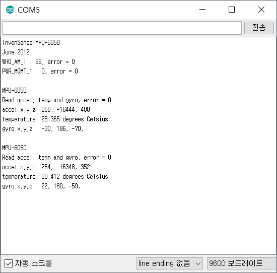
(2) 실행 결과
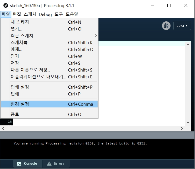
MPU6050과의 I2C 통신 상태를 검사하고 가속도, 자이로, 온도 값을 반복해서 보여준다.
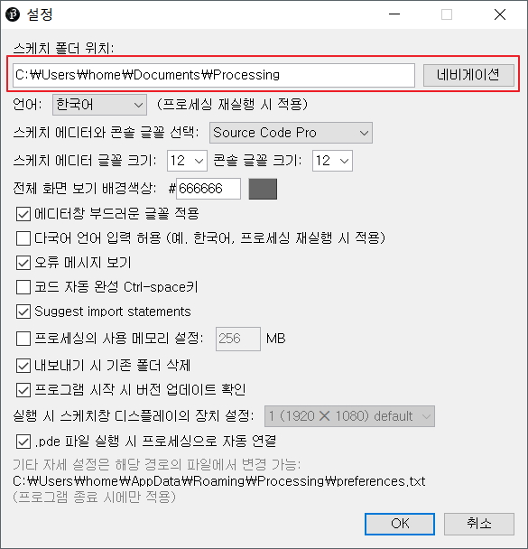
"스케치 폴더 위치/libraries" 폴더에
다운로드 받은 toxiclibs-complete-0020.zip 압축 파일을 해제해서 넣어 놓으면 된다. 라이브러리를 새로
설치하고 나면 프로세싱 프로그램을 종료하고 다시 시작해야 적용이 완료 된다.
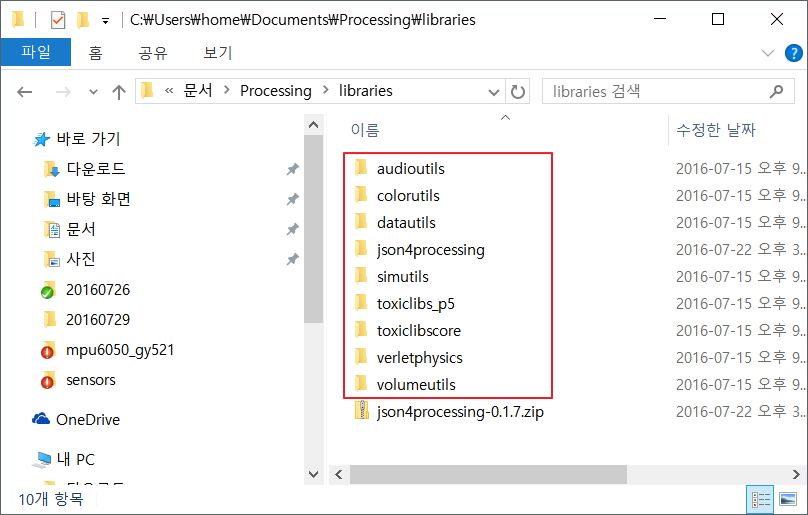
toxiclib 라이브러리가 모두 설치된
화면이다. 위 그림에서 json4processing 라이브러리는 본 예제를 실행 하는데는 필요하지 않다. 여기 까지 프로세싱
코드 실행을 위한 모든 준비가 되었다. 프로세싱코드는 MPUP6050 모듈에서 출력하는 데이터를 시리얼(RS232) 통신을
통해서 입력을 받아 데이터를 처리 하도록 되어 있다. 이제 아두이노와 MPU6050 모듈을 이용해서 프로세싱에서 처리 하기 위한
데이터 출력을 해보자.
3.2
아두이노 UNO R3 배선도
이전 예제 에서는 MPU6050의 INT 핀을 사용하지 않았는데 이번 예제에서는 아두이노에서
인터럽트를 사용하고 있기 때문에 INT핀을 아두이노의 D2핀에 연결을 해주었다. 나머지 배선도는 이전 예제와 동일하다.
3.3
아두이노 스케치 코드
(1) 아두이노 프로세싱 코드
프로세싱 코드에서 한가지 주의 해야할 사항은 처리 속도를 빠르게 하기 위해서 시리통 통신의 속도를 115200bps 로 설정을
하였다. 그렇기 때문에 아두이노의 시리얼 모니터창에서도 동일한 통신속도를 맞추어 주어야 한다.
// I2C device class (I2Cdev) demonstration Arduino sketch for MPU6050 class using DMP (MotionApps v2.0) // 6/21/2012 by Jeff Rowberg <jeff@rowberg.net> // Updates should (hopefully) always be available at https://github.com/jrowberg/i2cdevlib // // Changelog: // 2013-05-08 - added seamless Fastwire support // - added note about gyro calibration // 2012-06-21 - added note about Arduino 1.0.1 + Leonardo compatibility error // 2012-06-20 - improved FIFO overflow handling and simplified read process // 2012-06-19 - completely rearranged DMP initialization code and simplification // 2012-06-13 - pull gyro and accel data from FIFO packet instead of reading directly // 2012-06-09 - fix broken FIFO read sequence and change interrupt detection to RISING // 2012-06-05 - add gravity-compensated initial reference frame acceleration output // - add 3D math helper file to DMP6 example sketch // - add Euler output and Yaw/Pitch/Roll output formats // 2012-06-04 - remove accel offset clearing for better results (thanks Sungon Lee) // 2012-06-01 - fixed gyro sensitivity to be 2000 deg/sec instead of 250 // 2012-05-30 - basic DMP initialization working
/* ============================================ I2Cdev device library code is placed under the MIT license Copyright (c) 2012 Jeff Rowberg
Permission is hereby granted, free of charge, to any person obtaining a copy of this software and associated documentation files (the "Software"), to deal in the Software without restriction, including without limitation the rights to use, copy, modify, merge, publish, distribute, sublicense, and/or sell copies of the Software, and to permit persons to whom the Software is furnished to do so, subject to the following conditions:
The above copyright notice and this permission notice shall be included in all copies or substantial portions of the Software.
THE SOFTWARE IS PROVIDED "AS IS", WITHOUT WARRANTY OF ANY KIND, EXPRESS OR IMPLIED, INCLUDING BUT NOT LIMITED TO THE WARRANTIES OF MERCHANTABILITY, FITNESS FOR A PARTICULAR PURPOSE AND NONINFRINGEMENT. IN NO EVENT SHALL THE AUTHORS OR COPYRIGHT HOLDERS BE LIABLE FOR ANY CLAIM, DAMAGES OR OTHER LIABILITY, WHETHER IN AN ACTION OF CONTRACT, TORT OR OTHERWISE, ARISING FROM, OUT OF OR IN CONNECTION WITH THE SOFTWARE OR THE USE OR OTHER DEALINGS IN THE SOFTWARE. =============================================== */
// I2Cdev and MPU6050 must be installed as libraries, or else the .cpp/.h files // for both classes must be in the include path of your project #include "I2Cdev.h"
#include "MPU6050_6Axis_MotionApps20.h" //#include "MPU6050.h" // not necessary if using MotionApps include file
// Arduino Wire library is required if I2Cdev I2CDEV_ARDUINO_WIRE implementation // is used in I2Cdev.h #if I2CDEV_IMPLEMENTATION == I2CDEV_ARDUINO_WIRE #include "Wire.h" #endif
// class default I2C address is 0x68 // specific I2C addresses may be passed as a parameter here // AD0 low = 0x68 (default for SparkFun breakout and InvenSense evaluation board) // AD0 high = 0x69 MPU6050 mpu; //MPU6050 mpu(0x69); // <-- use for AD0 high
/* ========================================================================= NOTE: In addition to connection 3.3v, GND, SDA, and SCL, this sketch depends on the MPU-6050's INT pin being connected to the Arduino's external interrupt #0 pin. On the Arduino Uno and Mega 2560, this is digital I/O pin 2. * ========================================================================= */
/* ========================================================================= NOTE: Arduino v1.0.1 with the Leonardo board generates a compile error when using Serial.write(buf, len). The Teapot output uses this method. The solution requires a modification to the Arduino USBAPI.h file, which is fortunately simple, but annoying. This will be fixed in the next IDE release. For more info, see these links:
// uncomment "OUTPUT_READABLE_QUATERNION" if you want to see the actual // quaternion components in a [w, x, y, z] format (not best for parsing // on a remote host such as Processing or something though) //#define OUTPUT_READABLE_QUATERNION
// uncomment "OUTPUT_READABLE_EULER" if you want to see Euler angles // (in degrees) calculated from the quaternions coming from the FIFO. // Note that Euler angles suffer from gimbal lock (for more info, see // http://en.wikipedia.org/wiki/Gimbal_lock) //#define OUTPUT_READABLE_EULER
// uncomment "OUTPUT_READABLE_YAWPITCHROLL" if you want to see the yaw/ // pitch/roll angles (in degrees) calculated from the quaternions coming // from the FIFO. Note this also requires gravity vector calculations. // Also note that yaw/pitch/roll angles suffer from gimbal lock (for // more info, see: http://en.wikipedia.org/wiki/Gimbal_lock) #define OUTPUT_READABLE_YAWPITCHROLL
// uncomment "OUTPUT_READABLE_REALACCEL" if you want to see acceleration // components with gravity removed. This acceleration reference frame is // not compensated for orientation, so +X is always +X according to the // sensor, just without the effects of gravity. If you want acceleration // compensated for orientation, us OUTPUT_READABLE_WORLDACCEL instead. //#define OUTPUT_READABLE_REALACCEL
// uncomment "OUTPUT_READABLE_WORLDACCEL" if you want to see acceleration // components with gravity removed and adjusted for the world frame of // reference (yaw is relative to initial orientation, since no magnetometer // is present in this case). Could be quite handy in some cases. //#define OUTPUT_READABLE_WORLDACCEL
// uncomment "OUTPUT_TEAPOT" if you want output that matches the // format used for the InvenSense teapot demo #define OUTPUT_TEAPOT // processing
#define INTERRUPT_PIN 2 // use pin 2 on Arduino Uno & most boards #define LED_PIN 13 // (Arduino is 13, Teensy is 11, Teensy++ is 6) bool blinkState =false;
// MPU control/status vars bool dmpReady =false; // set true if DMP init was successful uint8_t mpuIntStatus; // holds actual interrupt status byte from MPU uint8_t devStatus; // return status after each device operation (0 = success, !0 = error) uint16_t packetSize; // expected DMP packet size (default is 42 bytes) uint16_t fifoCount; // count of all bytes currently in FIFO uint8_t fifoBuffer[64]; // FIFO storage buffer
// orientation/motion vars Quaternion q; // [w, x, y, z] quaternion container VectorInt16 aa; // [x, y, z] accel sensor measurements VectorInt16 aaReal; // [x, y, z] gravity-free accel sensor measurements VectorInt16 aaWorld; // [x, y, z] world-frame accel sensor measurements VectorFloat gravity; // [x, y, z] gravity vector float euler[3]; // [psi, theta, phi] Euler angle container float ypr[3]; // [yaw, pitch, roll] yaw/pitch/roll container and gravity vector
voidsetup() { // join I2C bus (I2Cdev library doesn't do this automatically) #if I2CDEV_IMPLEMENTATION == I2CDEV_ARDUINO_WIRE Wire.begin(); Wire.setClock(400000); // 400kHz I2C clock. Comment this line if having compilation difficulties #elif I2CDEV_IMPLEMENTATION == I2CDEV_BUILTIN_FASTWIRE Fastwire::setup(400, true); #endif
// initialize serial communication // (115200 chosen because it is required for Teapot Demo output, but it's // really up to you depending on your project) Serial.begin(115200); while (!Serial); // wait for Leonardo enumeration, others continue immediately
// NOTE: 8MHz or slower host processors, like the Teensy @ 3.3v or Ardunio // Pro Mini running at 3.3v, cannot handle this baud rate reliably due to // the baud timing being too misaligned with processor ticks. You must use // 38400 or slower in these cases, or use some kind of external separate // crystal solution for the UART timer.
// wait for ready Serial.println(F("\nSend any character to begin DMP programming and demo: ")); while (Serial.available() && Serial.read()); // empty buffer while (!Serial.available()); // wait for data while (Serial.available() && Serial.read()); // empty buffer again
// load and configure the DMP Serial.println(F("Initializing DMP...")); devStatus = mpu.dmpInitialize();
// supply your own gyro offsets here, scaled for min sensitivity mpu.setXGyroOffset(220); mpu.setYGyroOffset(76); mpu.setZGyroOffset(-85); mpu.setZAccelOffset(1788); // 1688 factory default for my test chip
// make sure it worked (returns 0 if so) if (devStatus ==0) { // turn on the DMP, now that it's ready Serial.println(F("Enabling DMP...")); mpu.setDMPEnabled(true);
// set our DMP Ready flag so the main loop() function knows it's okay to use it Serial.println(F("DMP ready! Waiting for first interrupt...")); dmpReady =true;
// get expected DMP packet size for later comparison packetSize = mpu.dmpGetFIFOPacketSize(); } else { // ERROR! // 1 = initial memory load failed // 2 = DMP configuration updates failed // (if it's going to break, usually the code will be 1) Serial.print(F("DMP Initialization failed (code ")); Serial.print(devStatus); Serial.println(F(")")); }
// configure LED for output pinMode(LED_PIN, OUTPUT); }
// ================================================================ // === MAIN PROGRAM LOOP === // ================================================================
voidloop() { // if programming failed, don't try to do anything if (!dmpReady) return;
// wait for MPU interrupt or extra packet(s) available while (!mpuInterrupt && fifoCount < packetSize) { // other program behavior stuff here // . // . // . // if you are really paranoid you can frequently test in between other // stuff to see if mpuInterrupt is true, and if so, "break;" from the // while() loop to immediately process the MPU data // . // . // . }
// reset interrupt flag and get INT_STATUS byte mpuInterrupt =false; mpuIntStatus = mpu.getIntStatus();
// get current FIFO count fifoCount = mpu.getFIFOCount();
// check for overflow (this should never happen unless our code is too inefficient) if ((mpuIntStatus &0x10) || fifoCount ==1024) { // reset so we can continue cleanly mpu.resetFIFO(); Serial.println(F("FIFO overflow!"));
// otherwise, check for DMP data ready interrupt (this should happen frequently) } elseif (mpuIntStatus &0x02) { // wait for correct available data length, should be a VERY short wait while (fifoCount < packetSize) fifoCount = mpu.getFIFOCount();
// read a packet from FIFO mpu.getFIFOBytes(fifoBuffer, packetSize);
// track FIFO count here in case there is > 1 packet available // (this lets us immediately read more without waiting for an interrupt) fifoCount -= packetSize;
#ifdef OUTPUT_READABLE_QUATERNION // display quaternion values in easy matrix form: w x y z mpu.dmpGetQuaternion(&q, fifoBuffer); Serial.print("quat\t"); Serial.print(q.w); Serial.print("\t"); Serial.print(q.x); Serial.print("\t"); Serial.print(q.y); Serial.print("\t"); Serial.println(q.z); #endif
// blink LED to indicate activity blinkState =!blinkState; digitalWrite(LED_PIN, blinkState); } }
(2) 실행 결과
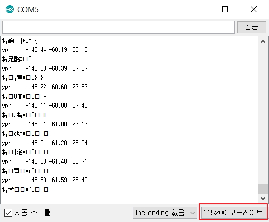
아두이노 시리얼 모니터창에서 반드시 보드레이트(Baudate)를 115200 으로 수정 해야 한다. 그렇지
않으면 시리얼 모니터 창에 아무런 데이터가 표시되지 않거나 잘못된 데이터가 표시될 것이다. 프로세싱 데이터를 처리하기 위한
데이터 이므로 데이터를 바로 판독하기는 어렵다. 데이터가 올바르게 표시되는것을 확인 하였다면 프로세싱에서 동일한 시리얼포트를
사용해야 하기 때문에 아두이노 시리얼 모니텅 창을 닫도록 하자.
3.4
프로세싱 코드
프로세싱 코드에서 한가지 주의 해야할 사항은 시리얼 포트를 각자의 환경에 맞추어서 수정을 해주어야 한다는 것이다.
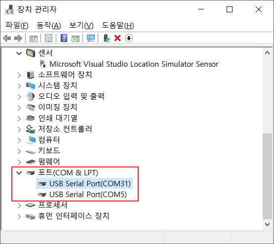
아래 프로세싱 코드에서 "[0]" 의 0이라는 숫자는 장치관리자에서 COM포트의 번호가 아니라 포트의 순서라는것에 주의 해야 한다.
위의 장치관리자 화면에서 예를 든다면 다음과 같다.
String portName = Serial.list()[0]; // --> COM31
String portName = Serial.list()[1]; // --> COM5

프로세싱 코드를 실행할때 테스트하는 PC의 COM 포트 상태에 따라서 "Serial.list()[0]" 의 숫자를 바꾸어 주어야 한다.
(1) 프로세싱 코드
// I2C device class (I2Cdev) demonstration Processing sketch for MPU6050 DMP output // 6/20/2012 by Jeff Rowberg <jeff@rowberg.net> // Updates should (hopefully) always be available at https://github.com/jrowberg/i2cdevlib // // Changelog: // 2012-06-20 - initial release
/* ============================================ I2Cdev device library code is placed under the MIT license Copyright (c) 2012 Jeff Rowberg
Permission is hereby granted, free of charge, to any person obtaining a copy of this software and associated documentation files (the "Software"), to deal in the Software without restriction, including without limitation the rights to use, copy, modify, merge, publish, distribute, sublicense, and/or sell copies of the Software, and to permit persons to whom the Software is furnished to do so, subject to the following conditions:
The above copyright notice and this permission notice shall be included in all copies or substantial portions of the Software.
THE SOFTWARE IS PROVIDED "AS IS", WITHOUT WARRANTY OF ANY KIND, EXPRESS OR IMPLIED, INCLUDING BUT NOT LIMITED TO THE WARRANTIES OF MERCHANTABILITY, FITNESS FOR A PARTICULAR PURPOSE AND NONINFRINGEMENT. IN NO EVENT SHALL THE AUTHORS OR COPYRIGHT HOLDERS BE LIABLE FOR ANY CLAIM, DAMAGES OR OTHER LIABILITY, WHETHER IN AN ACTION OF CONTRACT, TORT OR OTHERWISE, ARISING FROM, OUT OF OR IN CONNECTION WITH THE SOFTWARE OR THE USE OR OTHER DEALINGS IN THE SOFTWARE. =============================================== */
// NOTE: requires ToxicLibs to be installed in order to run properly. // 1. Download from http://toxiclibs.org/downloads // 2. Extract into [userdir]/Processing/libraries // (location may be different on Mac/Linux) // 3. Run and bask in awesomeness
ToxiclibsSupport gfx;
Serial port; // The serial port char[] teapotPacket =newchar[14]; // InvenSense Teapot packet int serialCount =0; // current packet byte position int synced =0; int interval =0;
// setup lights and antialiasing lights(); smooth();
// display serial port list for debugging/clarity println(Serial.list());
// get the first available port (use EITHER this OR the specific port code below) String portName = Serial.list()[0];
// get a specific serial port (use EITHER this OR the first-available code above) //String portName = "COM4";
// open the serial port port =new Serial(this, portName, 115200);
// send single character to trigger DMP init/start // (expected by MPU6050_DMP6 example Arduino sketch) port.write('r'); }
voiddraw() { if (millis() - interval >1000) { // resend single character to trigger DMP init/start // in case the MPU is halted/reset while applet is running port.write('r'); interval = millis(); }
// black background background(0);
// translate everything to the middle of the viewport pushMatrix(); translate(width /2, height /2);
// 3-step rotation from yaw/pitch/roll angles (gimbal lock!) // ...and other weirdness I haven't figured out yet //rotateY(-ypr[0]); //rotateZ(-ypr[1]); //rotateX(-ypr[2]);
// toxiclibs direct angle/axis rotation from quaternion (NO gimbal lock!) // (axis order [1, 3, 2] and inversion [-1, +1, +1] is a consequence of // different coordinate system orientation assumptions between Processing // and InvenSense DMP) float[] axis = quat.toAxisAngle(); rotate(axis[0], -axis[1], axis[3], axis[2]);
// draw main body in red fill(255, 0, 0, 200); box(10, 10, 200);
// draw front-facing tip in blue fill(0, 0, 255, 200); pushMatrix(); translate(0, 0, -120); rotateX(PI/2); drawCylinder(0, 20, 20, 8); popMatrix();