| |
4. Examples
4.1 GPIO Output without SDK
STM32F 시리즈에는 CPU Datasheet를 보지 않더라도 함수 이름만 보고서도 따라 할수 있을 정도의 ST사에서 제공하는 아주 훌륭한 Library 가 있습니다. 하지만 우리는 처음에는 STM32F CPU의 레지스터들을 더 잘 이해하기 위해서 SDK 라이브러리를 사용하지 않고 직접 SFR 레지스터드를 설정하는 방법으로 해보도록 하겠습니다.
첫번째 예제로 Dragon 개발보드의 Bottom 보드에 있는
LED들 중에서 LED2, LED4는 On, LED3 는 Off 시키는 예제를 해보도록 하겠습니다.
(1)
Dragon 개발보드의 LED 회로
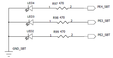
회로를 보면 LED를 켜기 위해서는 GPIO포트를 High로 하면 LED가 켜지도록 되어 있습니다.
(2) Peripheral Bus
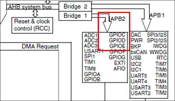
GPIOE 는 APB2 버스에 연결이 되어 있으므로 APB2 버스의 GPIOE 포트의 Clock을 Enable 시켜주어야 합니다.
(3) STM32 Peripheral Boundary Address : 0x4002 1000
( STM32F103 Reference Guide Page 50 )
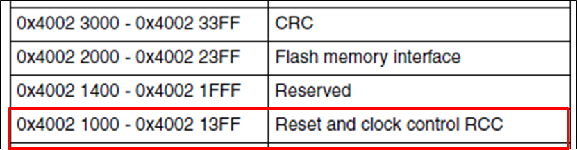
(4) RCC_APB2ENR Boundary Address : 0x4002 1000 + 0x18 ( STM32F103 Reference Guide Page 119 )
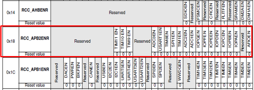
(5) RCC_APB2ENR Boundary Address : 0x4002 1018 ( STM32F103 Reference Guide Page 142 )
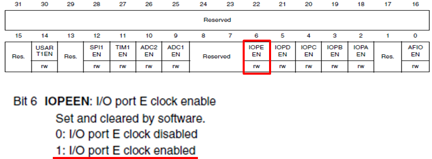
- GPIOE Port Enable : (*(volatile unsigned *)0x4002 1018) |= 0x01 << 6;
(6) GPIOE Port Boundary address : 0x4001 1800 ( STM32F103 Reference Guide Page 51 )
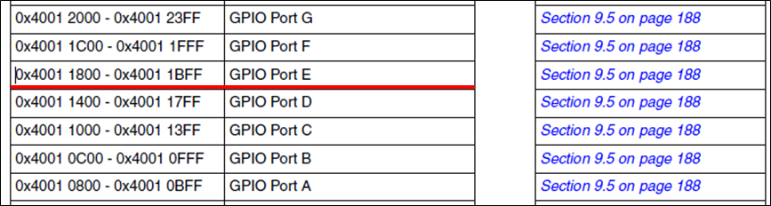
(7) GPIO and AFIO register maps ( STM32F103 Reference Guide Page 188 )

(8) GPIOE_CRL Register Boundary address : 0x4001 1800
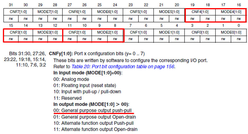
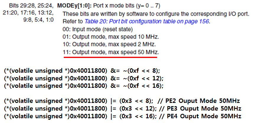
- GPIOE Port2, 3, 4 를 Output push-pull 로 설정
(9) GPIOE_BSRR(Set/Reset) Register Boundary address : 0x4001 1810
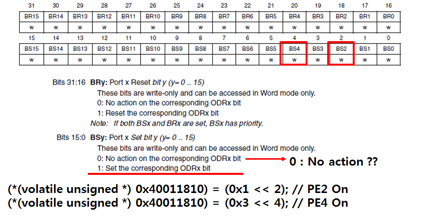
BSRR 레지스터는 GPIO Set or Reset 전용 레지스터 입니다. 0 ~ 15비트는 Set 전용이고 16 ~ 31비트는 Reset 레지스터 입니다.
LED2(GPIOE2), LED4(GPIOE4) 포트를 Set 하기위해서는 BSRR레지스터의 2, 4 번 비트를 1로 만들면 됩니다. "0"을 Write 했을때 "No action" 이라고 되어 있는 부분은 일반적으로 레지스터의 특정 비트를 Set or Clear 하기 위해서는 LDR, Bit 조작, STR 의 3단계가 필요한데, 이러한 Feature 가 지원이 되면 Bit 조작 다음에 바로 STR 명령어에 의해서 레지스터 비트 조작이 가능 하게 됩니다.
(10) GPIOE_BRR(Reset) Register Boundary address : 0x4001 1814
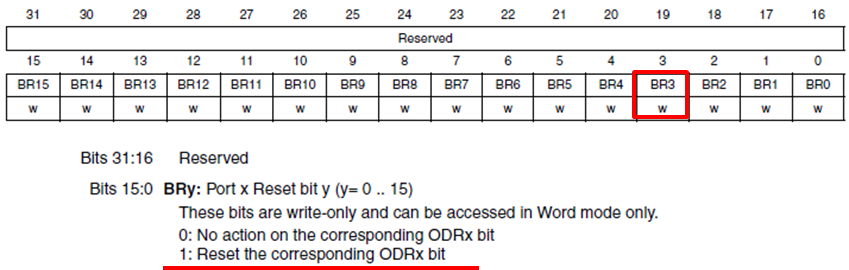
GPIO Reset 전용 레지스터를 이용해서 GPIOE3 을 Reset
합니다.
(*(volatile unsigned *) 0x40011814) = (0x1 << 3); // PE3 Off
* 예제 전체 코드
void led_test_wo_sdk(void)
{
// APB2 Clock enable
// Reference Page 47, 50, 119, 142
// APB2 peripheral GPIOE clock enable register (RCC_APB2ENR)
(*(volatile unsigned *)0x40021018) |= 0x01 << 6;
// General Purpose output push-pull
// Reference Page 51, 188, 166
// GPIOE_CRL
(*(volatile unsigned *)0x40011800) &= ~(0xf << 8);
(*(volatile unsigned *)0x40011800) &= ~(0xf << 12);
(*(volatile unsigned *)0x40011800) &= ~(0xf << 16);
// PE2, 3, 4 Ouput mode configuration
// Reference Page 51, 188, 166
// GPIOE_CRL
(*(volatile unsigned *)0x40011800) |= (0x3 << 8); // PE2 Ouput Mode 50MHz
(*(volatile unsigned *)0x40011800) |= (0x3 << 12); // PE3 Ouput Mode 50MHz
(*(volatile unsigned *)0x40011800) |= (0x3 << 16); // PE4 Ouput Mode 50MHz
// Reference Page 168
// GPIOE_BSRR
(*(volatile unsigned *)0x40011810) = (0x1 << 2); // PE2 On
// GPIOE_BSRR
(*(volatile unsigned *)0x40011810) = (0x1 << 4); // PE4 On
// GPIOE_BRR
(*(volatile unsigned *)0x40011814) = (0x1 << 3); // PE3 Off
}
|
4.2 GPIO Output with SDK
(1) 첫번째 예제와 동일한 동작을 하는데 이번에는 ST사에서 제공한 SDK 라이브러리를 이용해서 해보도록 하겠습니다.
(2) 프로젝트와 stm32f10x_conf.h 파일 수정
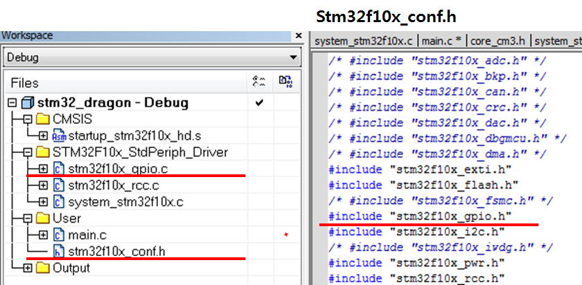
GPIO 라이브러리를 사용하기 위해서는 프로젝트에 stm32f10x_gpio.c 파일을 추가 하고 stm32f10x_conf.h 에서
stm32f10x_gpio.h 를 include 해야 합니다.
* 예제 전체 코드
void led_test_wt_sdk(void)
{
// Define GPIO Init structure
GPIO_InitTypeDef GPIO_InitStructure;
// APB2 Clock enable
RCC_APB2PeriphClockCmd(RCC_APB2Periph_GPIOE, ENABLE);
/* Configure the GPIOE ports for output*/
GPIO_InitStructure.GPIO_Pin = GPIO_Pin_2 | GPIO_Pin_3 | GPIO_Pin_4;
GPIO_InitStructure.GPIO_Speed = GPIO_Speed_50MHz;
GPIO_InitStructure.GPIO_Mode = GPIO_Mode_Out_PP;
GPIO_Init(GPIOE, &GPIO_InitStructure);
GPIO_SetBits(GPIOE, GPIO_Pin_2); // LED2 On
GPIO_ResetBits(GPIOE, GPIO_Pin_3); // LED3 Off
GPIO_SetBits(GPIOE, GPIO_Pin_4); // LED4 On
}
|
별도의 설명을 하지 않아도 함수의 이름만 봐도 쉽게 코드를 이해할수 있습니다.
4.3 GPIO Output with BitBand
(1) 예제 2번과 동일한 작업을 하는데, 이번에는 Bitband를 이용해서 해보도록 하겠습니다.
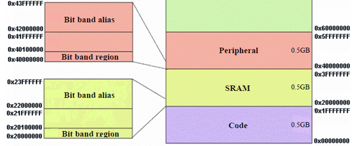
Peripheral 영역의 Bitband 영역을 이용해야하기 때문에 Bitband base 영역은 0x40000000 이 되고 Bitword base 는 0x42000000 이 됩니다.
Bitband 영역을 계산식을 다시한번 상기 하면서 소스코드를 분석해 보시기 바랍니다. GPIOE의 ODR 레지스터를 이용해서 구현 하였습니다.
bit_word_offset = (byte_offset x 32) + (bit_number × 4)
bit_word_addr = bit_band_base + bit_word_offset
// GPIOE_ODR : 0x4001180C
// 2,3,4 Bit : PE2, PE3, PE4
* 예제 전체 코드
#define PERI_BASE 0x40000000
#define PERI_BB_BASE 0x42000000
void led_test_wt_bitband(void)
{
// Define GPIO Init structure
GPIO_InitTypeDef GPIO_InitStructure;
// APB2 Clock enable
RCC_APB2PeriphClockCmd(RCC_APB2Periph_GPIOE, ENABLE);
/* Configure the GPIOE ports */
GPIO_InitStructure.GPIO_Pin = GPIO_Pin_2 | GPIO_Pin_3 | GPIO_Pin_4;
GPIO_InitStructure.GPIO_Speed = GPIO_Speed_50MHz;
GPIO_InitStructure.GPIO_Mode = GPIO_Mode_Out_PP;
GPIO_Init(GPIOE, &GPIO_InitStructure);
(*(volatile unsigned *)(PERI_BB_BASE + (0x4001180C-PERI_BASE)*32 + 2*4)) = 0x1; // PE2 On
(*(volatile unsigned *)(PERI_BB_BASE + (0x4001180C-PERI_BASE)*32 + 3*4)) = 0x0; // PE3 On
(*(volatile unsigned *)(PERI_BB_BASE + (0x4001180C-PERI_BASE)*32 + 4*4)) = 0x1; // PE4 On
}
|
4.4 GPIO Input - Polling
Dragon 개발보드에 있는 버튼 입력을 Polling 방식으로 처리해 보도록 하겠습니다.
(1) BTN2가 눌리면 LED2를 ON 시키고, BTN2가 눌리지 않은 상태면 LED2를 Off 합니다. 동일한 방법으로 BTN3, BTN4 에도 적용 합니다. 그리고 BTN1을 누르면 테스트를 종료 합니다.
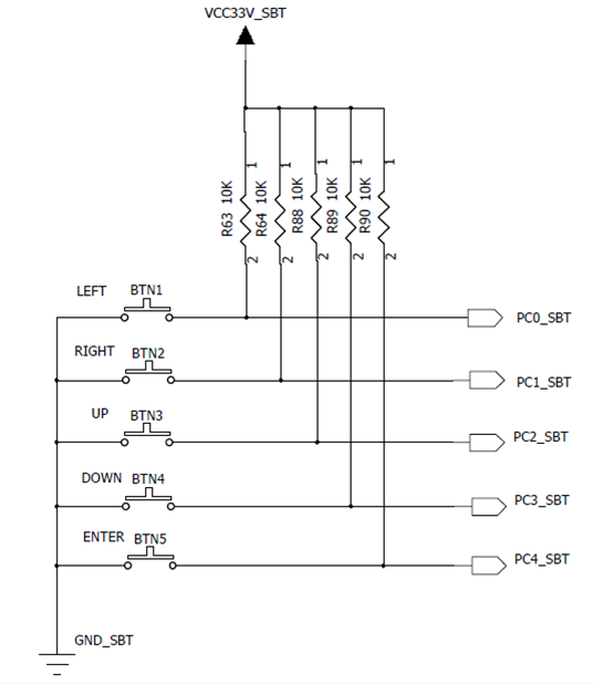
BTN 회로를 보면 버튼이 눌리지 않았을때는 VCC에 연결이 되어 High 상태이고 버튼이 눌리면 GND에 연결이 되면서 Low 상태가 됩니다.
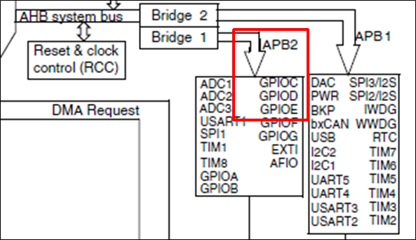
(2) GPIOC 그룹을 사용하기 위해서는 APB2 버스의 GPIOC 그룹의 Clock을 Enable 해야 합니다.
(3) GPIOC1, 2, 3 을 Input floating 으로 설정 합니다.
* 예제 전체 코드
void key_input_test_polling_wt_sdk(void)
{
// Define GPIO Init structure
GPIO_InitTypeDef GPIO_InitStructure;
// APB2 Clock enable for LED
RCC_APB2PeriphClockCmd(RCC_APB2Periph_GPIOE, ENABLE);
// APB2 Clock enable for KEY
RCC_APB2PeriphClockCmd(RCC_APB2Periph_GPIOC, ENABLE);
/* Configure the GPIOE ports for output*/
GPIO_InitStructure.GPIO_Pin = GPIO_Pin_2 | GPIO_Pin_3 | GPIO_Pin_4;
GPIO_InitStructure.GPIO_Speed = GPIO_Speed_50MHz;
GPIO_InitStructure.GPIO_Mode = GPIO_Mode_Out_PP;
GPIO_Init(GPIOE, &GPIO_InitStructure);
/* Configure the GPIOC ports for input */
GPIO_InitStructure.GPIO_Pin = GPIO_Pin_0 | GPIO_Pin_1 | GPIO_Pin_2 | GPIO_Pin_3;
GPIO_InitStructure.GPIO_Speed = GPIO_Speed_10MHz;
GPIO_InitStructure.GPIO_Mode = GPIO_Mode_IN_FLOATING;
GPIO_Init(GPIOC, &GPIO_InitStructure);
while(1)
{
// BTN1
if( (!GPIO_ReadInputDataBit(GPIOC, GPIO_Pin_0 )) )
{
break;
}
// BTN2
if( (!GPIO_ReadInputDataBit(GPIOC, GPIO_Pin_1 )) )
{
GPIO_SetBits(GPIOE, GPIO_Pin_2); // LED2 On
}
else
{
GPIO_ResetBits(GPIOE, GPIO_Pin_2); // LED2 Off
}
// BTN3
if( (!GPIO_ReadInputDataBit(GPIOC, GPIO_Pin_2 )) )
{
GPIO_SetBits(GPIOE, GPIO_Pin_3); // LED3 On
}
else
{
GPIO_ResetBits(GPIOE, GPIO_Pin_3); // LED3 Off
}
// BTN4
if( (!GPIO_ReadInputDataBit(GPIOC, GPIO_Pin_3 )) )
{
GPIO_SetBits(GPIOE, GPIO_Pin_4); // LED4 On
}
else
{
GPIO_ResetBits(GPIOE, GPIO_Pin_4); // LED4 Off
}
}
}
|
4.5 GPIO Input - Interrupt
이번에는 BTN 입력을 폴링 방식이 아닌 인터럽트 방식으로 구현해 보도록 하겠습니다.
(1) BTN2를 한번 누르면 LED2를 On 시키고, 다시 BTN2를 누르면 LED2를 Off 합니다.
(2) BTN 입력을 Falling Edge 에서 검출되도록 설정 합니다. Falling Edge 에서 검출한다는 것은 KEY Down에서 인터럽트가 발생하도록 한다는 것이죠.
KEY Up을 검출하기 위해서는 Rising Edge 에서 검출되도록 설정하면 됩니다.
(3) PC1 포트의 인터럽트 입력을 받으려면 외부 인터럽트 1번에 연결해야 합니다. 당연히 PC2는 외부 인터럽트 2번에 연결해야 하겠죠.
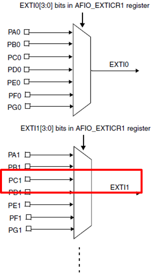
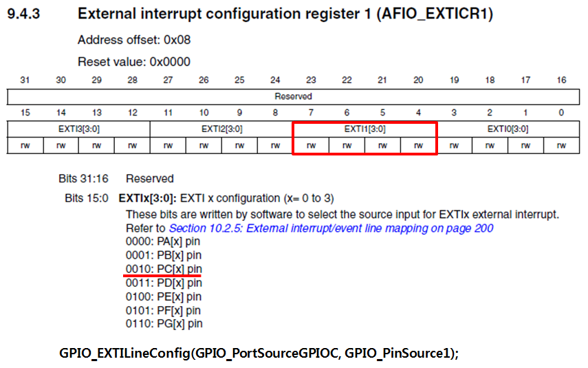
(4) 인터럽트 레지스터 설정
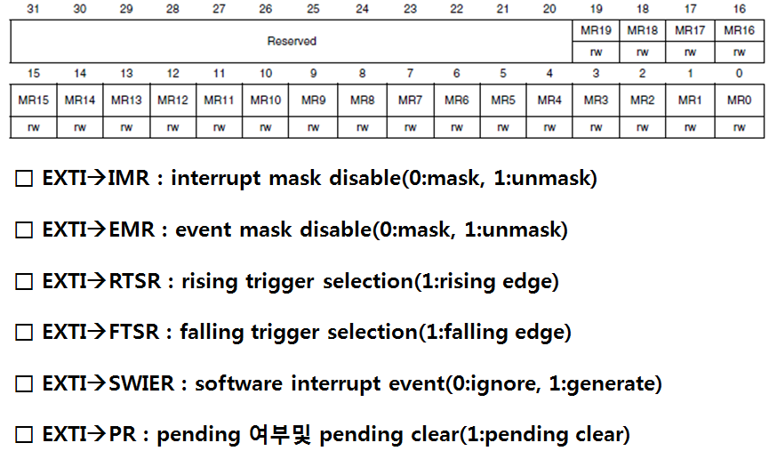
(5) SDK 라이브러리 추가
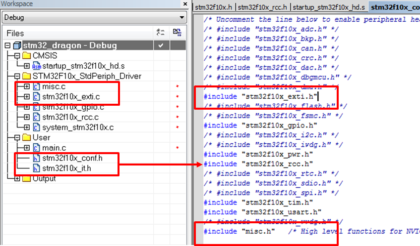
(6) 인터럽트 우선순위
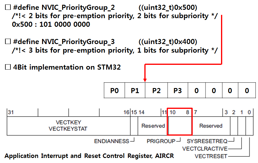
STM32에서 인터럽트 우선순위 비트는 8비트중에서 상위 4비트만 사용을 합니다. 4비트 중에서 이번 예제에서는 Priority group 2를 사용해서 Group우선순위 2비트 Sub 우선순위 2비트를 사용하도록 설정 합니다.
(7) 인터럽트 서비스 흐름도
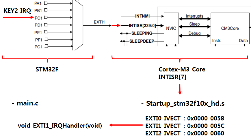
외부 인터럽트가 발생해서 인터럽트 핸들러 함수로 분기하기 까지의 과정을 도식화 해보았습니다.
(8) 예제 코드 작성 순서
□ APB2 Clock enable for LED
□ APB2 Clock enable for KEY
□ Configure the GPIOE ports for output
□ Configure the GPIOC ports for input
□ Configure EXTI to generate an interrupt on falling edge
□ EXTIPR : pending 여부및 pending clear(1:pending clear)
□ ICPR : pending clear Cortex-M3
* 예제 전체 코드
void key_input_test_interrupt(void)
{
EXTI_InitTypeDef EXTI_InitStructure;
NVIC_InitTypeDef NVIC_InitStructure;
// Define GPIO Init structure
GPIO_InitTypeDef GPIO_InitStructure;
// APB2 Clock enable for LED
RCC_APB2PeriphClockCmd(RCC_APB2Periph_GPIOE, ENABLE);
// APB2 Clock enable for KEY
RCC_APB2PeriphClockCmd(RCC_APB2Periph_GPIOC, ENABLE);
// for Interrupt
RCC_APB2PeriphClockCmd(RCC_APB2Periph_AFIO, ENABLE);
/* Configure the GPIOE ports for output*/
GPIO_InitStructure.GPIO_Pin = GPIO_Pin_2 | GPIO_Pin_3 | GPIO_Pin_4;
GPIO_InitStructure.GPIO_Speed = GPIO_Speed_50MHz;
GPIO_InitStructure.GPIO_Mode = GPIO_Mode_Out_PP;
GPIO_Init(GPIOE, &GPIO_InitStructure);
/* Configure the GPIOC ports for input */
GPIO_InitStructure.GPIO_Pin = GPIO_Pin_0 | GPIO_Pin_1 | GPIO_Pin_2 | GPIO_Pin_3;
GPIO_InitStructure.GPIO_Speed = GPIO_Speed_10MHz;
GPIO_InitStructure.GPIO_Mode = GPIO_Mode_IN_FLOATING;
GPIO_Init(GPIOC, &GPIO_InitStructure);
/* Connect EXTI */
// External Interrupt configuration register1 (AFIO_EXTICR1)
GPIO_EXTILineConfig(GPIO_PortSourceGPIOC, GPIO_PinSource1);
/* Configure EXTI1 to generate an interrupt on falling edge */
EXTI_InitStructure.EXTI_Line = EXTI_Line1;
EXTI_InitStructure.EXTI_Mode = EXTI_Mode_Interrupt;
EXTI_InitStructure.EXTI_Trigger = EXTI_Trigger_Falling;
EXTI_InitStructure.EXTI_LineCmd = ENABLE;
EXTI_Init(&EXTI_InitStructure);
// 2 bit for pre-emption priority, 2 bits for subpriority
NVIC_PriorityGroupConfig(NVIC_PriorityGroup_2);
NVIC_InitStructure.NVIC_IRQChannel = EXTI1_IRQn;
NVIC_InitStructure.NVIC_IRQChannelPreemptionPriority = 1;
NVIC_InitStructure.NVIC_IRQChannelSubPriority = 1;
NVIC_InitStructure.NVIC_IRQChannelCmd = ENABLE;
NVIC_Init(&NVIC_InitStructure);
/* Clear EXTI Line Pending Bit */
// STM32F10x Pending Register : 0x40010400 + 0x14
EXTI_ClearITPendingBit(EXTI_Line1);
/* Enable the Key EXTI line Interrupt */
// Cortex-M3 Interrupt Clear-Pending Register : 0xE000E280-0xE000E29C
NVIC_ClearPendingIRQ(EXTI1_IRQn);
}
void EXTI1_IRQHandler(void)
{
if(EXTI_GetITStatus(EXTI_Line1) != RESET)
{
EXTI_ClearITPendingBit(EXTI_Line1);
// Blink
GPIOE->ODR ^= (0x1 << 2);
}
}
|
4.6 General Purpose Timer
임베디드 시스템에서 Timer는 가장 중요하고 필수적인 요소로 OS에서 Task 스케줄링을 위해서 사용되기도 하고, 전자액자, 차량용 블랙박스 등의 응용 어플리케이션에서도 특정 시간 이후에 인터럽트를 발생시켜 정해진 일을 수행하는 경우등 응용분야는 무수히 많습니다.
- 참고 -
CPU의 클럭 속도가 1Hz 라는 것은 무엇을 의미하는 것일까요 ?
이것은 1초에 1번의 Tick 이 발생한다는 것임. STM32가 72MHz 로 동작 한다면 1초에 7천2백만번의 Tick이 발생하는 것
이번 예제에서는 STM32 CPU에 내장된 Timer2를 이용해서 1초에 한번씩 Timer 인터럽트를 발생시켜 LDE2, LED3 를 Toggle(On/Off 를 반복하는것) 하는 실험을 해보도록 하겠습니다.
- 참고 -
1sec = 1,000ms = 1,000,000us = 1,000,000,000ns
1Hz = 1KHz = 1MHz = 1GHz
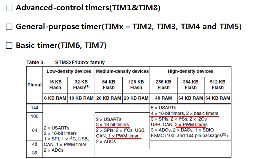
(1) STM32F CPU의 타이머 종류
(2) Timer Clock
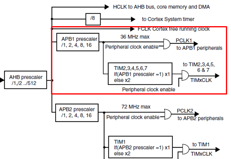
Timer2는 APB1 버스에 연결되어 있습니다. APB1 버스의 최대 동작 속도는 36MHz 이지만 위이 그림을 잘 보면 APB1 의 Prescaler가 1이 아니면 PB1 Clock x2 를 하고 있습니다. 그러므로 Timer2가 APB1에 연결되어 있지만 Timer2에 공급되는 Clock 은 72MHz 가 됩니다. 주의해서 보지 않으면 Timer2에 공급되는 Clock이 36MHz 라고 착각 할수 있습니다.
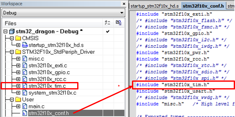
(3) 프로젝트와 stm32f10x_conf.h 파일 수정
(4) 예제 코드 작성 순서
□ APB1 Clock enable for TIM2
□ GPIO Init for LED
□ Configure the TIM2 interrupt
□ Time base configuration
□ TIM2 Enable
□ TIM2 interrupt enable
* 예제 전체 코드
void gpio_init_led(void)
{
// Define GPIO Init structure
GPIO_InitTypeDef GPIO_InitStructure;
// APB2 Clock enable
RCC_APB2PeriphClockCmd(RCC_APB2Periph_GPIOE, ENABLE);
/* Configure the GPIOE ports for output*/
GPIO_InitStructure.GPIO_Pin = GPIO_Pin_2 | GPIO_Pin_3 | GPIO_Pin_4;
GPIO_InitStructure.GPIO_Speed = GPIO_Speed_50MHz;
GPIO_InitStructure.GPIO_Mode = GPIO_Mode_Out_PP;
GPIO_Init(GPIOE, &GPIO_InitStructure);
}
void gpio_init_key(void)
{
// Define GPIO Init structure
GPIO_InitTypeDef GPIO_InitStructure;
// APB2 Clock enable for KEY
RCC_APB2PeriphClockCmd(RCC_APB2Periph_GPIOC, ENABLE);
// for Interrupt
RCC_APB2PeriphClockCmd(RCC_APB2Periph_AFIO, ENABLE);
/* Configure the GPIOC ports for input */
GPIO_InitStructure.GPIO_Pin = GPIO_Pin_0 | GPIO_Pin_1 | GPIO_Pin_2 | GPIO_Pin_3;
GPIO_InitStructure.GPIO_Speed = GPIO_Speed_10MHz;
GPIO_InitStructure.GPIO_Mode = GPIO_Mode_IN_FLOATING;
GPIO_Init(GPIOC, &GPIO_InitStructure);
}
void TIM2_IRQHandler(void)
{
if(TIM_GetITStatus(TIM2, TIM_IT_Update) != RESET )
{
// Also cleared the wrong interrupt flag in the ISR
TIM_ClearFlag(TIM2, TIM_FLAG_Update);
TIM_ClearITPendingBit(TIM2, TIM_IT_Update); // Clear the interrupt flag
// Blink
GPIOE->ODR ^= (0x1 << 2);
GPIOE->ODR ^= (0x1 << 3);
}
}
void timer2_test(void)
{
NVIC_InitTypeDef NVIC_InitStructure;
TIM_TimeBaseInitTypeDef TIM_TimeBaseStructure;
/* TIM2 clock enable */
RCC_APB1PeriphClockCmd(RCC_APB1Periph_TIM2, ENABLE);
gpio_init_led();
/* Enable the TIM2 global Interrupt */
NVIC_InitStructure.NVIC_IRQChannel = TIM2_IRQn;
NVIC_InitStructure.NVIC_IRQChannelPreemptionPriority = 1;
NVIC_InitStructure.NVIC_IRQChannelSubPriority = 1;
NVIC_InitStructure.NVIC_IRQChannelCmd = ENABLE;
NVIC_Init(&NVIC_InitStructure);
// TIM2CLK = 72 MHz( APB1은 원래 36MHz 인데 분주를 해서 사용하므로 36*2 = 72MHz 가 된다. )
// 시간의 기본단위 :S(초)-->nS.uS.mS.S.
// 72000000/60000=1200 즉 1초에 1200번 클럭이 발생하므로
// ARR 레지스터를 1199+1 번에 한번 인터럽트가
// 발생하도록 설정하면 1초에 한번 인터럽트가 발생된다.
/* Time base configuration */
TIM_TimeBaseStructure.TIM_Period = 1200-1; // ARR(Auto reload register)
TIM_TimeBaseStructure.TIM_Prescaler = 60000-1;
TIM_TimeBaseStructure.TIM_ClockDivision = TIM_CKD_DIV1;
TIM_TimeBaseStructure.TIM_CounterMode = TIM_CounterMode_Up;
TIM_TimeBaseInit(TIM2, &TIM_TimeBaseStructure);
TIM_ARRPreloadConfig(TIM2, ENABLE);
TIM_Cmd(TIM2, ENABLE);
/* TIM IT enable */
TIM_ITConfig(TIM2, TIM_IT_Update , ENABLE);
}
|
자주 사용하는 LED, KEY 포트를 초기화 하는 함수 gpio_init_led, gpio_init_key 를 만들어서 호출 하였습니다.
4.7 Systick - Delay
SysTick Timer를 이용해서 1us Delay 함수를 구현하자. delay_ms 함수를 이용하여 LDE2, LED3 을 1초 간격으로 Toggle(On/Off) 해 봅시다.
(1) System Control Space
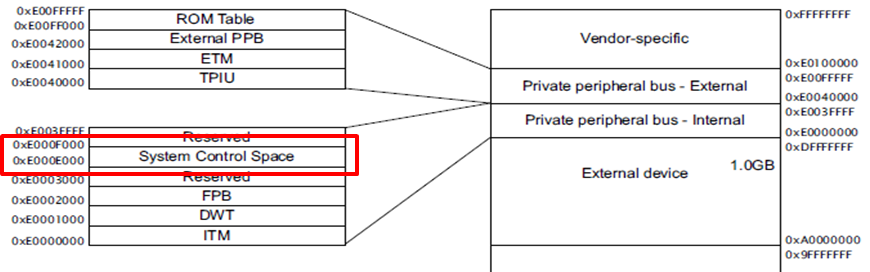
System timer 인 SysTick 은 System Control Space 영역에 위치하고 있습니다.
(2)
SysTick Control and Status Register
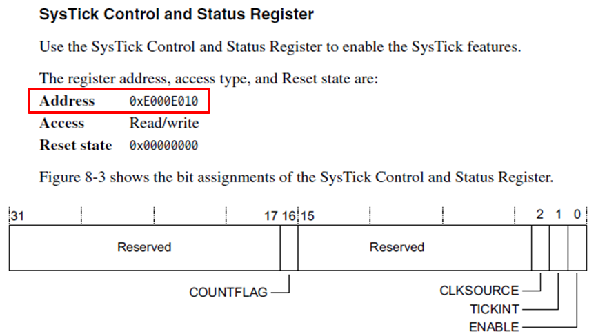
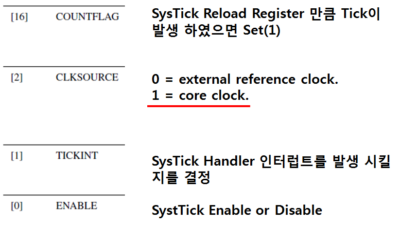
이번에는 SysTick 인터럽트는 사용하지 않을 것이오 CLKSOURCE는 core clock(72MHz) 을 그대로 사용할 것입니다.
(3) Systick Reload Register
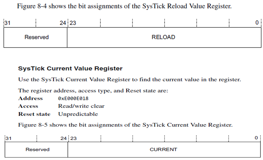
Systick Current Value Register를 보면 Systick Timer 는 24비트 타이머 라는것을 알수 있습니다.
* 예제 전체 코드
// 1us delay 함수
void delay_us (const uint32_t usec)
{
RCC_ClocksTypeDef RCC_Clocks;
/* Configure HCLK clock as SysTick clock source */
SysTick_CLKSourceConfig(SysTick_CLKSource_HCLK);
RCC_GetClocksFreq(&RCC_Clocks);
// Set SysTick Reload(1us) register and Enable
// usec * (RCC_Clocks.HCLK_Frequency / 1000000) < 0xFFFFFFUL -- because of 24bit timer
// RCC_Clocks.HCLK_Frequency = 72000000
// Systick Reload Value Register = 72
// 72 / 72000000 = 1us
SysTick_Config(usec * (RCC_Clocks.HCLK_Frequency / 1000000));
// SysTick Interrupt Disable
SysTick->CTRL &= ~SysTick_CTRL_TICKINT_Msk ;
// Until Tick count is 0
while (!(SysTick->CTRL & SysTick_CTRL_COUNTFLAG_Msk));
}
// 1ms delay 함수
void delay_ms (const uint32_t msec)
{
delay_us(1000 * msec);
}
void systick_test_delay(void)
{
gpio_init_led();
gpio_init_key();
while(1)
{
// BTN1
if( (!GPIO_ReadInputDataBit(GPIOC, GPIO_Pin_0 )) )
{
break;
}
delay_ms(100);
delay_ms(100);
delay_ms(100);
delay_ms(100);
delay_ms(100);
delay_ms(100);
delay_ms(100);
delay_ms(100);
delay_ms(100);
delay_ms(100);
// Blink
GPIOE->ODR ^= (0x1 << 2);
GPIOE->ODR ^= (0x1 << 3);
}
}
|
72MHz 클럭을 가지는 24Bit SysTick 타이머로는 1초 Delay를 만들어 낼수 없기 때문에 100msec delay 함수를 10번 호출하여 구현하였습니다.
4.8 Systick - Interrupt
SysTick Timer를 이용해서 100msec 간격으로 SysTick_Handler 인터럽트를 발생 시키고 LDE2, LED3 을 Toggle(On/Off) 해 봅시다.
* 예제 전체 코드
void SysTick_Handler(void)
{
// Blink
GPIOE->ODR ^= (0x1 << 2);
GPIOE->ODR ^= (0x1 << 3);
}
void systick_test_interrupt(void)
{
RCC_ClocksTypeDef RCC_Clocks;
gpio_init_led();
/* Configure HCLK clock as SysTick clock source */
SysTick_CLKSourceConfig(SysTick_CLKSource_HCLK);
RCC_GetClocksFreq(&RCC_Clocks);
/* Setup SysTick Timer for 100 msec interrupts */
if (SysTick_Config(RCC_Clocks.HCLK_Frequency / 10))
{
/* Capture error */
while (1);
}
}
|
SysTick_Config 함수안에서 기본으로 SysTick 인터럽트를 Enable 하고 있기 때문에 다른 설정을 하지 않아도 SysTick_Handler 인터럽트 핸들러로 진입 합니다.
이전 SysTick Delay 예제 에서는 인터럽트가 발생하지 않도록 하기 위해서
SysTick->CTRL &= ~SysTick_CTRL_TICKINT_Msk ;
위와 같은 코드가 삽입이 되어 있었습니다.
4.9 USART - Polling
UART1를 PC와 115200bps Baudrate로 통신(RX, TX)을 하는 Echo server로 만들어 봅시다.
RX, TX 통신을 폴링 방식으로 처리 합니다. 터미널에서 ‘x’ 가 입력되면 폴링을 종료 합니다.
(1) Dragon 개발보드의 UART 회로
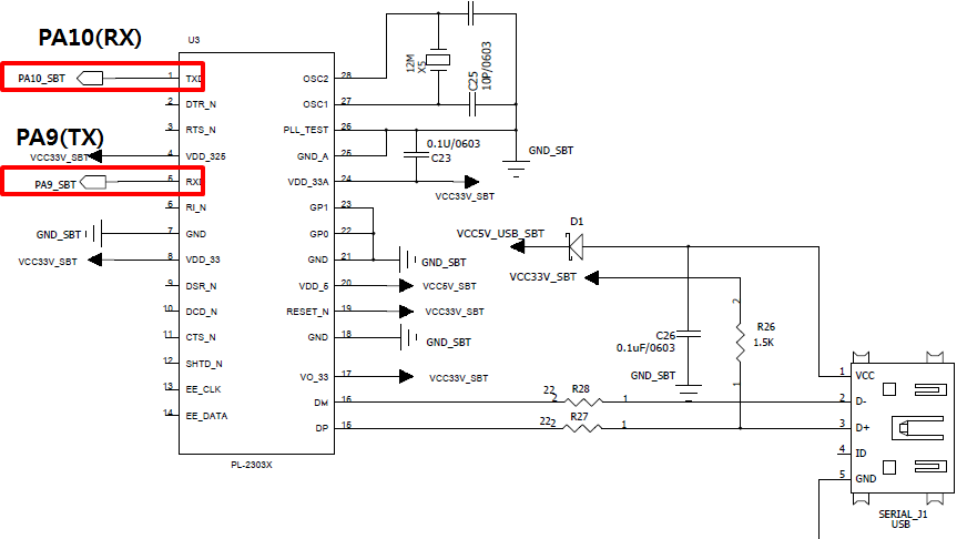
Dragon 개발보드에는 COM포트가 없는 노트북, 데스크탑에서 편리하게 사용하게 하기 위해서 USB to Serial 포트가 내장되어 있습니다.
회로도를 보면 PA10이 RX, PA9가 TX 포트 입니다. 이번 예제 테스트를 위해서 단순히 USB 미니케이블을 이용해서 Dragon Bottom 보드에 있는 UART0번과 PCB 의 USB 포트에 연결을 하면 됩니다. 이때 아직 USB to Serial USB 드라이버를 설치하지 않았다면 이전 강좌에서 설명한 "PL2303 USB to Serial 드라이버 설치" 부분을 참조 하시기 바랍니다.
(2) Peripheral Bus
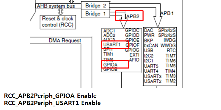
APB2 버스에 연결되어 있는 USART1과 GPA9, 10 번 포트도 사용되고 있기 때문에 2개의 Peripheral Clock 을 모두 Enable해 주어야 합니다.
(3) UART1 사용을 위한 GPIO 포트 초기화
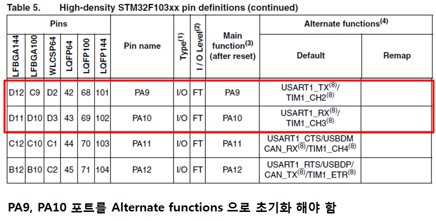
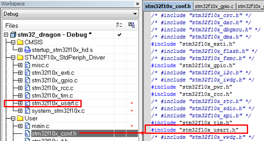
(4) 프로젝트와 stm32f10x_conf.h 파일 수정
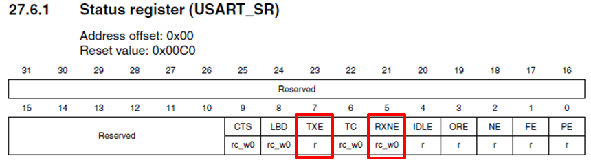
(5) USART Status register
* 예제 전체 코드
void usart1_test_polling(void)
{
GPIO_InitTypeDef GPIO_InitStructure;
USART_InitTypeDef USART_InitStructure;
char receive_data;
// APB2 Clock enable for USART(GPIOA9, A10)
RCC_APB2PeriphClockCmd(RCC_APB2Periph_GPIOA, ENABLE);
/* USART1 clock enable */
RCC_APB2PeriphClockCmd(RCC_APB2Periph_USART1, ENABLE);
/* Configure the GPIO ports( USART1 Transmit and Receive Lines) */
/* Configure the USART1_Tx as Alternate function Push-Pull */
GPIO_InitStructure.GPIO_Pin = GPIO_Pin_9;
GPIO_InitStructure.GPIO_Speed = GPIO_Speed_50MHz;
GPIO_InitStructure.GPIO_Mode = GPIO_Mode_AF_PP;
GPIO_Init(GPIOA, &GPIO_InitStructure);
/* Configure the USART1_Rx as input floating */
GPIO_InitStructure.GPIO_Pin = GPIO_Pin_10;
GPIO_InitStructure.GPIO_Mode = GPIO_Mode_IN_FLOATING;
GPIO_Init(GPIOA, &GPIO_InitStructure);
/* Configure the USART1 */
USART_InitStructure.USART_BaudRate = 115200;
USART_InitStructure.USART_WordLength = USART_WordLength_8b;
USART_InitStructure.USART_StopBits = USART_StopBits_1;
USART_InitStructure.USART_Parity = USART_Parity_No;
USART_InitStructure.USART_HardwareFlowControl = USART_HardwareFlowControl_None;
USART_InitStructure.USART_Mode = USART_Mode_Rx | USART_Mode_Tx;
USART_Init(USART1, &USART_InitStructure);
/* Enable the USART1 */
USART_Cmd(USART1, ENABLE);
while(1)
{
// Rx not empty 가 될때까지 Polling
while(USART_GetFlagStatus(USART1, USART_FLAG_RXNE) == RESET );
// Rx not empty가 되면 USART Data register 에서 data를 읽어옴
receive_data = USART_ReceiveData(USART1) & 0xFF;
// Tx data 전송
USART_SendData(USART1, receive_data);
// Tx empty가 상태가 될때까지 Polling
// Tx 전송시 이 코드를 생략하면 빠른 Data 전송시 중간에 Tx Data 가 유실될수 있음
while(USART_GetFlagStatus(USART1, USART_FLAG_TXE) == RESET );
if( receive_data == 'x' )
break;
}
}
|
4.10 USART - Interrupt
UART1를 PC와 115200bps Baudrate로 통신(RX, TX)을 하는 Echo server로 만들어 봅시다. TX 는 폴링 방식으로 처리 하고 RX는 Interrupt 방식으로 처리 합니다.
(1) USART1 Control Register
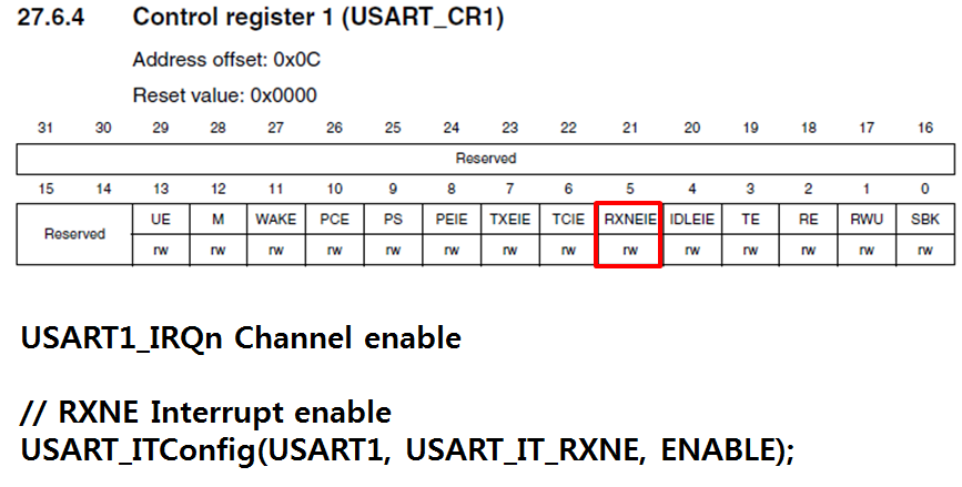
* 예제 전체 코드
void USART1_IRQHandler(void)
{
char receive_data;
if(USART_GetITStatus(USART1, USART_IT_RXNE) != RESET)
{
receive_data = USART_ReceiveData(USART1) & 0xFF;
USART_SendData(USART1, receive_data);
while(USART_GetFlagStatus(USART1, USART_FLAG_TXE) == RESET );
USART_ClearITPendingBit(USART1, USART_IT_RXNE);
}
}
void usart1_test_interrupt(void)
{
GPIO_InitTypeDef GPIO_InitStructure;
USART_InitTypeDef USART_InitStructure;
NVIC_InitTypeDef NVIC_InitStructure;
// APB2 Clock enable for USART(GPIOA9, A10)
RCC_APB2PeriphClockCmd(RCC_APB2Periph_GPIOA, ENABLE);
/* USART1 clock enable */
RCC_APB2PeriphClockCmd(RCC_APB2Periph_USART1, ENABLE);
/* Enable the USART1 Interrupt */
NVIC_InitStructure.NVIC_IRQChannel = USART1_IRQn;
NVIC_InitStructure.NVIC_IRQChannelPreemptionPriority = 1;
NVIC_InitStructure.NVIC_IRQChannelSubPriority = 1;
NVIC_InitStructure.NVIC_IRQChannelCmd = ENABLE;
NVIC_Init(&NVIC_InitStructure);
/* Configure the GPIO ports( USART1 Transmit and Receive Lines) */
/* Configure the USART1_Tx as Alternate function Push-Pull */
GPIO_InitStructure.GPIO_Pin = GPIO_Pin_9;
GPIO_InitStructure.GPIO_Speed = GPIO_Speed_50MHz;
GPIO_InitStructure.GPIO_Mode = GPIO_Mode_AF_PP;
GPIO_Init(GPIOA, &GPIO_InitStructure);
/* Configure the USART1_Rx as input floating */
GPIO_InitStructure.GPIO_Pin = GPIO_Pin_10;
GPIO_InitStructure.GPIO_Mode = GPIO_Mode_IN_FLOATING;
GPIO_Init(GPIOA, &GPIO_InitStructure);
/* Configure the USART1 */
USART_InitStructure.USART_BaudRate = 115200;
USART_InitStructure.USART_WordLength = USART_WordLength_8b;
USART_InitStructure.USART_StopBits = USART_StopBits_1;
USART_InitStructure.USART_Parity = USART_Parity_No;
USART_InitStructure.USART_HardwareFlowControl = USART_HardwareFlowControl_None;
USART_InitStructure.USART_Mode = USART_Mode_Rx | USART_Mode_Tx;
USART_Init(USART1, &USART_InitStructure);
// Rx Not empty interrupt enable
USART_ITConfig(USART1, USART_IT_RXNE, ENABLE);
/* Enable the USART1 */
USART_Cmd(USART1, ENABLE);
}
|
4.11 USART - Name Card
PC의 터미널에 다음과 같이 명함을 출력해 보세요.
*************************************
* Name : Kyung Yeon Kim *
* Company : JK Electronics *
* No : 010-XXXX-XXXX *
*************************************
참고1) 터미널의 행 개행 문자는 “\r\n”
참고2) 터미널 문자열 출력을 하는데 문자열 출력 함수를 만들 어 사용하세요.
void usart1_send_string(char *data);
참고3) usart1 초기(폴링방식)화 함수를 작성하세요.
void usart1_init(void);
* 예제 전체 코드
void usart1_init(void)
{
GPIO_InitTypeDef GPIO_InitStructure;
USART_InitTypeDef USART_InitStructure;
// APB2 Clock enable for USART(GPIOA9, A10)
RCC_APB2PeriphClockCmd(RCC_APB2Periph_GPIOA, ENABLE);
/* USART1 clock enable */
RCC_APB2PeriphClockCmd(RCC_APB2Periph_USART1, ENABLE);
/* Configure the GPIO ports( USART1 Transmit and Receive Lines) */
/* Configure the USART1_Tx as Alternate function Push-Pull */
GPIO_InitStructure.GPIO_Pin = GPIO_Pin_9;
GPIO_InitStructure.GPIO_Speed = GPIO_Speed_50MHz;
GPIO_InitStructure.GPIO_Mode = GPIO_Mode_AF_PP;
GPIO_Init(GPIOA, &GPIO_InitStructure);
/* Configure the USART1_Rx as input floating */
GPIO_InitStructure.GPIO_Pin = GPIO_Pin_10;
GPIO_InitStructure.GPIO_Mode = GPIO_Mode_IN_FLOATING;
GPIO_Init(GPIOA, &GPIO_InitStructure);
/* Configure the USART1 */
USART_InitStructure.USART_BaudRate = 115200;
USART_InitStructure.USART_WordLength = USART_WordLength_8b;
USART_InitStructure.USART_StopBits = USART_StopBits_1;
USART_InitStructure.USART_Parity = USART_Parity_No;
USART_InitStructure.USART_HardwareFlowControl = USART_HardwareFlowControl_None;
USART_InitStructure.USART_Mode = USART_Mode_Rx | USART_Mode_Tx;
USART_Init(USART1, &USART_InitStructure);
/* Enable the USART1 */
USART_Cmd(USART1, ENABLE);
}
void usart1_send_string(char* data)
{
while(*data != '\0')
{
USART_SendData(USART1, *(unsigned char *)data);
while(USART_GetFlagStatus(USART1, USART_FLAG_TXE) == RESET );
data++;
}
}
void usart1_test_namecard(void)
{
usart1_init();
usart1_send_string("\r\n");
usart1_send_string("****************************************\r\n");
usart1_send_string("* Name : Kyung Yeon Kim *\r\n");
usart1_send_string("* Company : JK Electronics *\r\n");
usart1_send_string("* No : 010-XXXX-XXXX *\r\n");
usart1_send_string("****************************************\r\n");
usart1_send_string("\r\n");
}
|
4.12 Interrupt Priority1
BTN3를 누르면 LED3 를 무한 반복을 하면서 On 을 시키고 BTN4를 누르면 LED4 를 무한 반복을 하면서 On 을 시킨다.
(1) Group, Sub Priority bit 를 각각 2Bit씩 설정
(2) BTN3의 Group Priority를 2, Sub Priority를 0로 설정
(3) BTN4의 Group Priority를 1, Sub Priority를 0로 설정 후 테스트
* 예제 전체 코드
void EXTI2_IRQHandler(void)
{
if(EXTI_GetITStatus(EXTI_Line2) != RESET)
{
EXTI_ClearITPendingBit(EXTI_Line2);
while(1)
{
GPIO_SetBits(GPIOE, GPIO_Pin_3); // LED3 On
}
}
}
void EXTI3_IRQHandler(void)
{
if(EXTI_GetITStatus(EXTI_Line3) != RESET)
{
EXTI_ClearITPendingBit(EXTI_Line3);
while(1)
{
GPIO_SetBits(GPIOE, GPIO_Pin_4); // LED4 On
}
}
}
void interrupt_priority1_test(void)
{
EXTI_InitTypeDef EXTI_InitStructure;
NVIC_InitTypeDef NVIC_InitStructure;
gpio_init_led();
gpio_init_key();
/* Connect EXTI */
// External Interrupt configuration register1 (AFIO_EXTICR1)
GPIO_EXTILineConfig(GPIO_PortSourceGPIOC, GPIO_PinSource2);
GPIO_EXTILineConfig(GPIO_PortSourceGPIOC, GPIO_PinSource3);
/* Configure EXTI2 to generate an interrupt on falling edge */
EXTI_InitStructure.EXTI_Line = EXTI_Line2;
EXTI_InitStructure.EXTI_Mode = EXTI_Mode_Interrupt;
EXTI_InitStructure.EXTI_Trigger = EXTI_Trigger_Falling;
EXTI_InitStructure.EXTI_LineCmd = ENABLE;
EXTI_Init(&EXTI_InitStructure);
/* Configure EXTI3 to generate an interrupt on falling edge */
EXTI_InitStructure.EXTI_Line = EXTI_Line3;
EXTI_InitStructure.EXTI_Mode = EXTI_Mode_Interrupt;
EXTI_InitStructure.EXTI_Trigger = EXTI_Trigger_Falling;
EXTI_InitStructure.EXTI_LineCmd = ENABLE;
EXTI_Init(&EXTI_InitStructure);
// 2 bit for pre-emption priority, 2 bits for subpriority
NVIC_PriorityGroupConfig(NVIC_PriorityGroup_2);
NVIC_InitStructure.NVIC_IRQChannel = EXTI2_IRQn;
NVIC_InitStructure.NVIC_IRQChannelPreemptionPriority = 2;
NVIC_InitStructure.NVIC_IRQChannelSubPriority = 0;
NVIC_InitStructure.NVIC_IRQChannelCmd = ENABLE;
NVIC_Init(&NVIC_InitStructure);
NVIC_InitStructure.NVIC_IRQChannel = EXTI3_IRQn;
NVIC_InitStructure.NVIC_IRQChannelPreemptionPriority = 1;
NVIC_InitStructure.NVIC_IRQChannelSubPriority = 0;
NVIC_InitStructure.NVIC_IRQChannelCmd = ENABLE;
NVIC_Init(&NVIC_InitStructure);
/* Clear EXTI Line Pending Bit */
// STM32F10x Pending Register : 0x40010400 + 0x14
EXTI_ClearITPendingBit(EXTI_Line2);
EXTI_ClearITPendingBit(EXTI_Line3);
/* Enable the Key EXTI line Interrupt */
// Cortex-M3 Interrupt Clear-Pending Register : 0xE000E280-0xE000E29C
NVIC_ClearPendingIRQ(EXTI2_IRQn);
NVIC_ClearPendingIRQ(EXTI3_IRQn);
}
|
예제의 실행결과를 알수 있게죠. BTN3의 Group Priority를 2로 BTN4보다 높기 때문에 BTN3을 먼저 누르면 BTN4의 인터럽트가 실행되지 못합니다. 반대로 BTN4의 인터럽트 실행중에 BTN3을 누르면 즉시 BTN3의 인터럽트 서비스 루틴이 실행 됩니다.
4.13 Interrupt Priority2
BTN3를 누르면 LED3 를 무한 반복을 하면서 On 을 시키고 BTN4를 누르면 LED4 를 무한 반복을 하면서 On 을 시킨다.
(1) Group, Sub Priority bit 를 각각 2Bit씩 설정
(2) BTN3의 Group Priority를 2, Sub Priority를 0로 설정
(3) BTN4의 Group Priority를 2, Sub Priority를 1로 설정 후 테스트
* 예제 전체 코드
void EXTI2_IRQHandler(void)
{
if(EXTI_GetITStatus(EXTI_Line2) != RESET)
{
EXTI_ClearITPendingBit(EXTI_Line2);
while(1)
{
GPIO_SetBits(GPIOE, GPIO_Pin_3); // LED3 On
}
}
}
void EXTI3_IRQHandler(void)
{
if(EXTI_GetITStatus(EXTI_Line3) != RESET)
{
EXTI_ClearITPendingBit(EXTI_Line3);
while(1)
{
GPIO_SetBits(GPIOE, GPIO_Pin_4); // LED4 On
}
}
}
void interrupt_priority1_test(void)
{
EXTI_InitTypeDef EXTI_InitStructure;
NVIC_InitTypeDef NVIC_InitStructure;
gpio_init_led();
gpio_init_key();
/* Connect EXTI */
// External Interrupt configuration register1 (AFIO_EXTICR1)
GPIO_EXTILineConfig(GPIO_PortSourceGPIOC, GPIO_PinSource2);
GPIO_EXTILineConfig(GPIO_PortSourceGPIOC, GPIO_PinSource3);
/* Configure EXTI2 to generate an interrupt on falling edge */
EXTI_InitStructure.EXTI_Line = EXTI_Line2;
EXTI_InitStructure.EXTI_Mode = EXTI_Mode_Interrupt;
EXTI_InitStructure.EXTI_Trigger = EXTI_Trigger_Falling;
EXTI_InitStructure.EXTI_LineCmd = ENABLE;
EXTI_Init(&EXTI_InitStructure);
/* Configure EXTI3 to generate an interrupt on falling edge */
EXTI_InitStructure.EXTI_Line = EXTI_Line3;
EXTI_InitStructure.EXTI_Mode = EXTI_Mode_Interrupt;
EXTI_InitStructure.EXTI_Trigger = EXTI_Trigger_Falling;
EXTI_InitStructure.EXTI_LineCmd = ENABLE;
EXTI_Init(&EXTI_InitStructure);
// 2 bit for pre-emption priority, 2 bits for subpriority
NVIC_PriorityGroupConfig(NVIC_PriorityGroup_2);
NVIC_InitStructure.NVIC_IRQChannel = EXTI2_IRQn;
NVIC_InitStructure.NVIC_IRQChannelPreemptionPriority = 2;
NVIC_InitStructure.NVIC_IRQChannelSubPriority = 0;
NVIC_InitStructure.NVIC_IRQChannelCmd = ENABLE;
NVIC_Init(&NVIC_InitStructure);
NVIC_InitStructure.NVIC_IRQChannel = EXTI3_IRQn;
NVIC_InitStructure.NVIC_IRQChannelPreemptionPriority = 2;
NVIC_InitStructure.NVIC_IRQChannelSubPriority = 1;
NVIC_InitStructure.NVIC_IRQChannelCmd = ENABLE;
NVIC_Init(&NVIC_InitStructure);
/* Clear EXTI Line Pending Bit */
// STM32F10x Pending Register : 0x40010400 + 0x14
EXTI_ClearITPendingBit(EXTI_Line2);
EXTI_ClearITPendingBit(EXTI_Line3);
/* Enable the Key EXTI line Interrupt */
// Cortex-M3 Interrupt Clear-Pending Register : 0xE000E280-0xE000E29C
NVIC_ClearPendingIRQ(EXTI2_IRQn);
NVIC_ClearPendingIRQ(EXTI3_IRQn);
}
|
이번 예제에서는 BTN3과 4의 Group우선순위가 같기 때문에 서로 인터럽트 수행중에는 선점을 하지 못합니다.
4.14 Power Management - Sleep
Cortex-M3 에서 Power Management 기능은 NVIC에 포함되어 있습니다.
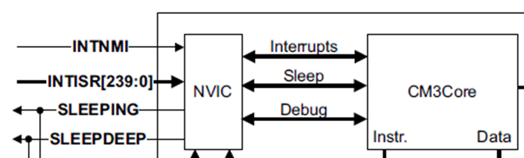
(1) Sleep 모드 테스트
터미널 창에 아래와 같이 표시 되도록 합니다.
Entered Sleep mode.
__WFI(); // Sleep mode 로 진입
Exit Sleep mode.
(2) BTN2 를 인터럽트 모드로 입력 받아서 Sleep 모드를 빠져 나오도록 합니다. 추가로 BTN2를 누르면 LED2를 On 시키고 BTN2를 떼면 LED2를 Off 합니다.
(3) STM32F Low Power Mode
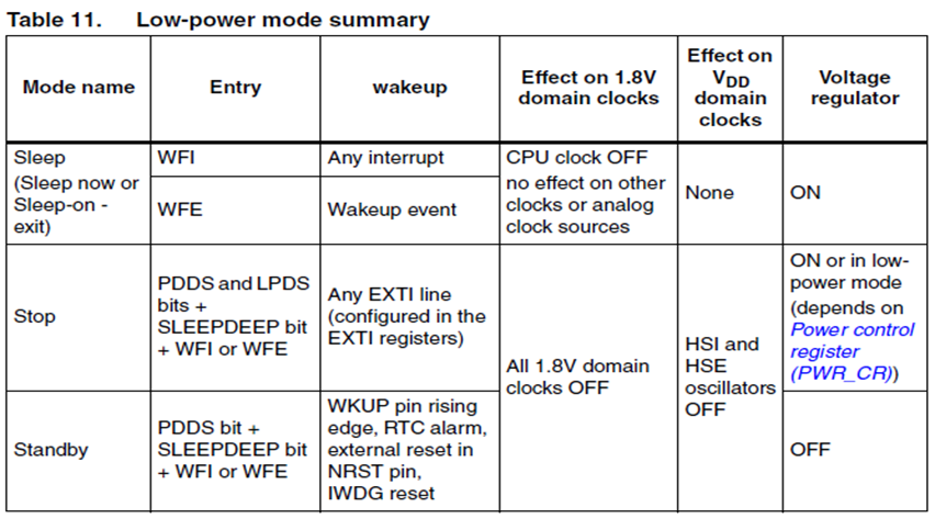
STM32 에서 Sleep 모드로 진입하기 위해서는 WFI(Wait for Interrupt) or WFE(Wait for Event) 어셈블리어에 의해서 진입할 수 있습니다. 이번 예제에서는 WFI 를 이용해서 Sleep 모드로 진입 하도록 하겠습니다.
WFI에 의해서 진입한 Sleep 모드에서 깨어나기 위해서는 어떠한 인터럽트 발생에 의해서라도 깨어 날수 있습니다.
* 예제 전체 코드
void power_management_sleep_test(void)
{
key_input_test_interrupt();
usart1_send_string("\r\nEnter Sleep mode.\r\n");
__WFI();
usart1_send_string("\r\nExit Sleep mode.\r\n");
}
|
Sleep 모드의 장점은 Cortex-M3 Core의 Clock만 멈추어 있는 상태여서 인터럽트에 의해서 즉시 깨어날수가 있어서 Sleep 모드에 진입해 있는지 조차 알수가 없다는 것이고 단점은 Stop, StandBy 모드에 비해서 소모전류가 많다는 것입니다.
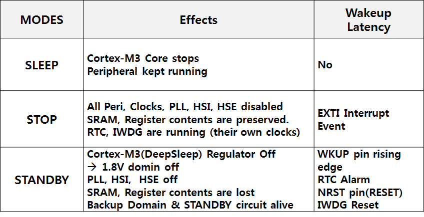
Sleep 모드별 Wakeup 방식과 Clock Management 방법입니다.
4.15 Power Management - Stop
Stop, StnadBy 모드는 모두 Cortex-M3 Deep sleep 모드에 해당 합니다.
(1) Stop 모드 실험
□ Timer2 인터럽트를 1초 간격으로 발생 시켜 LED2, LED3 를 Toggle
□ PWR_EnterSTOPMode() 함수를 호출하여 Stop 모드로 진입 합니다.
□ BTN2 를 인터럽트 모드로 입력 받아서 Stop 모드를 빠져 나오도록 합니다. 추가로 BTN2를 누르면 LED2를 On 시키고 BTN2를 떼면 LED2를 Off 합니다.
□ STOP 모드를 빠져나온 이후에 LED2, LED3이 1초 간격으로 Toggle
□ PWR_EnterSTOPMode를 호출하면 진입
□ SRAM, Register 상태는 유지
□ 1.8V Domain에 있는 모든 클럭이 Stop
□ PLL, HIS RC, HSE crystal oscillator 모두 disable
□ Voltage regulator는 normal or low power mode
□ Wakeup
□ EXTI line 중의 하나를 받아야 함
□ 16개의 EXTI line or PVD ouput, RTC alarm, USB wakeup
(2) Peripheral Bus - PWR

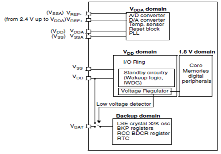
STM32F 의 Power 블럭은 APB1 버스에 연결되어 있습니다.
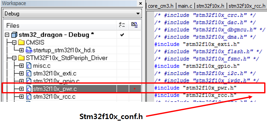
(3) 프로젝트와 stm32f10x_conf.h 파일 수정
(4) STM32 PWR 블럭도
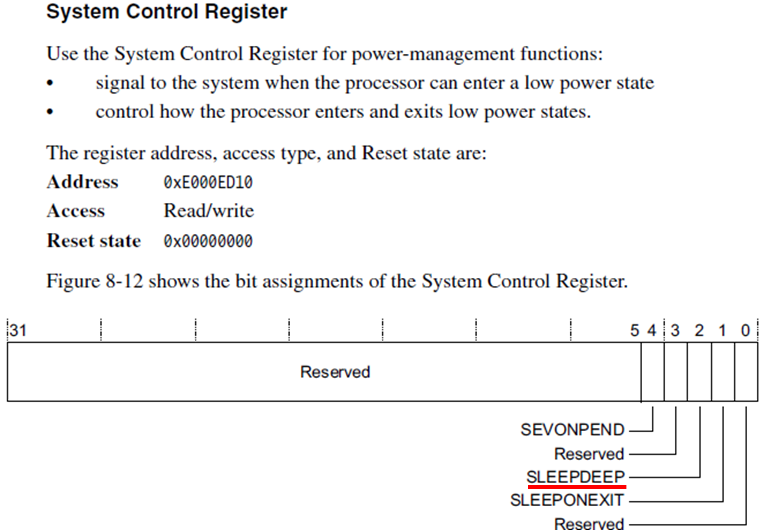
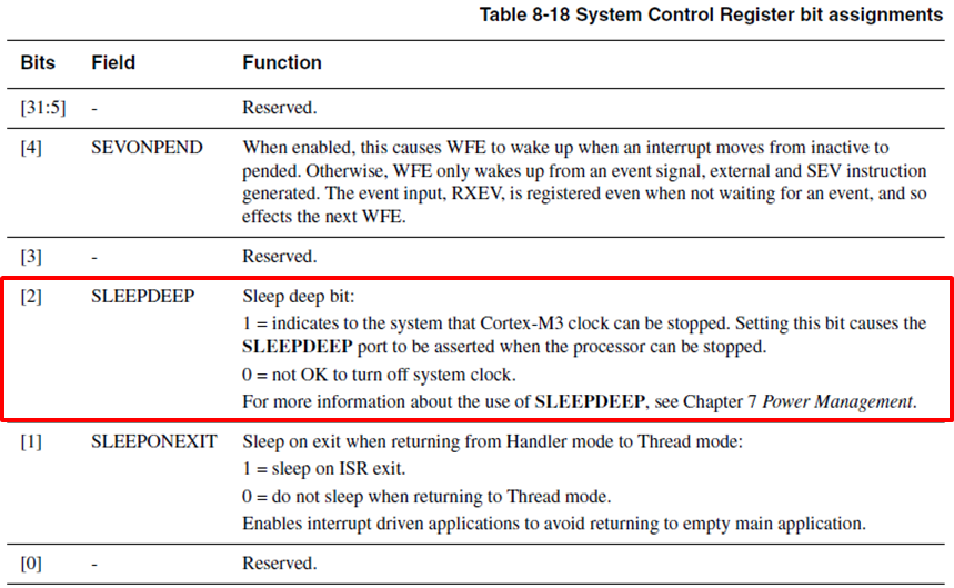
(5) Cortex-M3 System Control Register
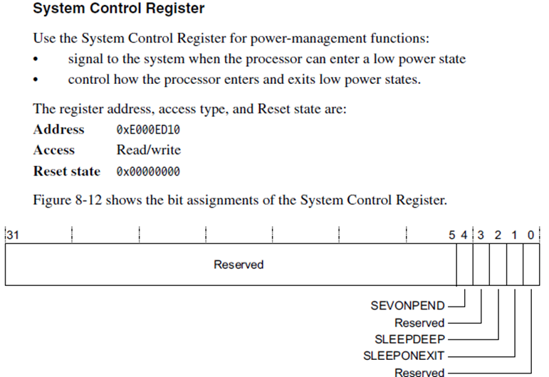
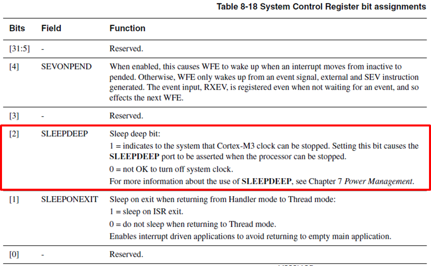
Stop 모드로 진입 시키기 위해서는 2번 비트의 SLEEPDEEP 을 Set 해야 합니다.
(6) STM32 Power Control Register
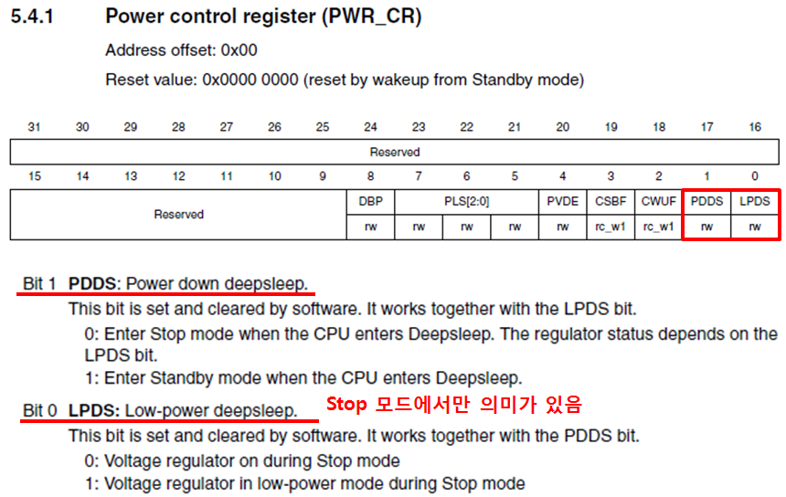
PDDS를 0으로, LPDS를 0으로 할수도 있고, 1로 할수도 있으나 이번 예제에서는 1로 설정하여 Vdd Domain에 있는 Voltage Regulator를 low-power 모드로 설정 합니다.
* 예제 전체 코드
// STOP 모드에 진입하면 HSE Clock 등이 Disale 되기 때문에 Wakeup시에 다시 설정을 해주어야 합니다.
void system_clock_config_stop(void)
{
RCC_HSEConfig(RCC_HSE_ON); // Enable HSE
if( RCC_WaitForHSEStartUp() == SUCCESS)
{
RCC_PLLCmd(ENABLE); // Enable PLL
// Wait until PLL is ready
while(RCC_GetFlagStatus(RCC_FLAG_PLLRDY) == RESET) {}
// Select PLL as system clock source
RCC_SYSCLKConfig(RCC_SYSCLKSource_PLLCLK);
// wait until PLL is used as system clock source
while(RCC_GetSYSCLKSource() != 0x08) {}
}
}
void power_management_stop_test(void)
{
RCC_APB1PeriphClockCmd(RCC_APB1Periph_PWR, ENABLE);
timer2_test();
key_input_test_interrupt();
usart1_send_string("\r\nEnter Stop mode.\r\n");
// STOP 모드로 진입하고 외부 인터럽트에 의해서 깨어남
PWR_EnterSTOPMode(PWR_Regulator_LowPower, PWR_STOPEntry_WFI);
system_clock_config_stop();
usart1_send_string("\r\nExit Stop mode.\r\n");
}
|
4.16 Power Management - StandBy
(1) PWR_WakeUpPinCmd(ENABLE) 를 호출, PA0를 Wakeup 핀으로 설정
(2) BTN2 를 인터럽트 모드로 입력 받아서 Stop 모드를 빠져나오도록 설정
(3) PWR_EnterSTANDBYMode()를 호출, StandBy 모드로 진입
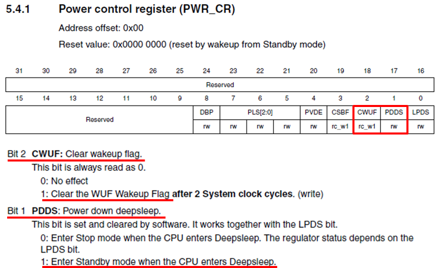
StandBy 모드로 진입하는 방법은 STOP모드로 진입하는 방법에서 STM32의 PWR_CR 레지스터의 PDDS 를 1로 설정하는것을 제외하면 동일 합니다. 단지 StandBy 모드에서는 Wakeup 하는 방법에서 차기가 있으면 StandBy 모드에서 Wakeup을 한다는 것은 CPU가 처음부터 다시 부팅하는 절차와 동일 합니다. 하지만 StandBy 모드에서 Wakeup이 되는 경우에는 PWR_CSR 레지스터의 Standby Flag가 H/W 적으로 Set이 되어 있습니다.
(4) Power Control Register
(5) System Control Register
(6) Enable Wakeup PIN
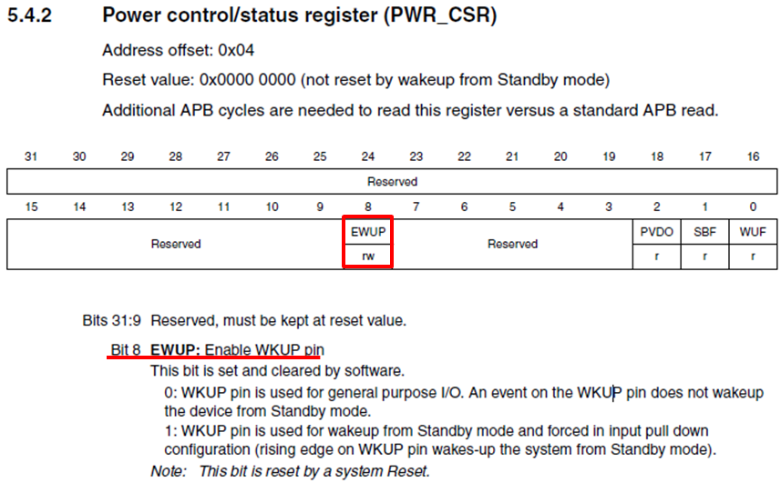
StandBy 모드에서 깨어나기 위해서 Wakeup 핀을 Enable 합니다. 반드시 PA0 핀이 이용 됩니다.
(7) Power control/status register
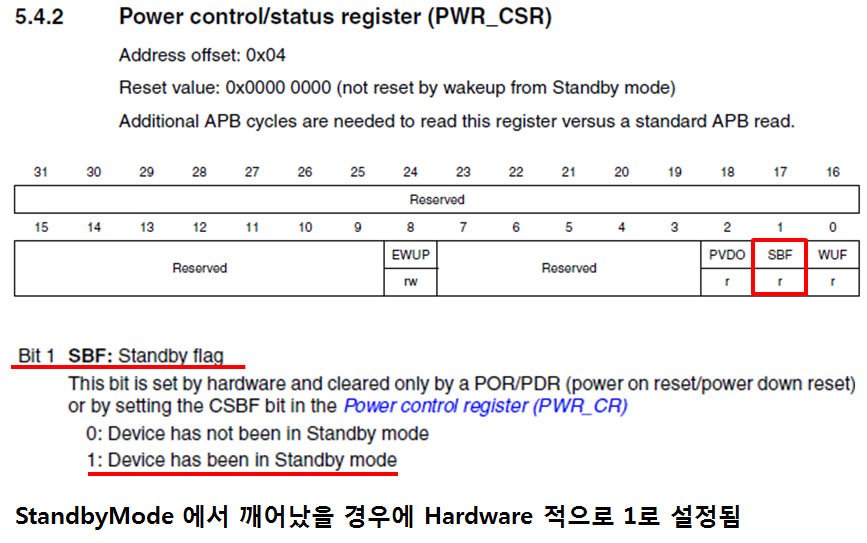
* 예제 전체 코드
void power_management_standby_test(void)
{
RCC_APB1PeriphClockCmd(RCC_APB1Periph_PWR, ENABLE);
// Enable Wakeup Pin(should be PA0)
PWR_WakeUpPinCmd(ENABLE);
usart1_send_string("\r\nWakeup pin enabled.\r\n");
usart1_send_string("Enter Standby mode.\r\n");
// Standby Mode
PWR_EnterSTANDBYMode();
// 이 코드는 실행될수 없음
usart1_send_string("\r\nExit Standby mode.\r\n");
}
|
4.17 Mode Privilege
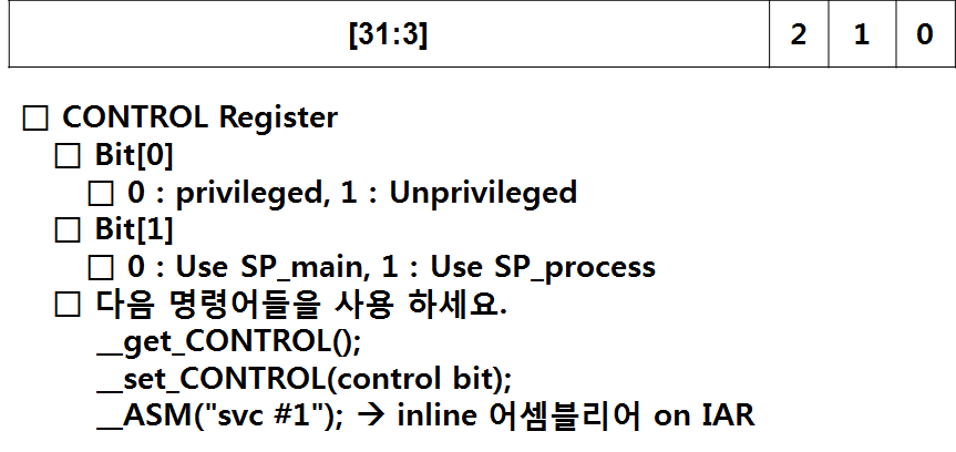
(1) Reset 이후의 Mode(Privilege or Unprivilege)와 어떤 Stack을 (Main Stack, Process Stack) 사용하는지를 PC의 터미널에 표시를 합니다.
(2) Mode를 Unprivilege 모드로 전환 합니다.
(3) 모든 전환 이후에 Mode(Privilege or Unprivilege)와 어떤 Stack을 (Main Stack, Process Stack) 사용하는지를 PC의 터미널에 표시를 합니다.
(4) SVC 명령어 “__ASM("svc #1")” 를 사용해서 SVC_Handler Exception을 발생시키고 SVC_Handler 핸들러 진입 여부를 터미널에 표시 합니다.
(5) SVC 핸들러내에서 Mode를 Privilege 모드로 전환 합니다.
(6) 모든 전환 이후에 Mode(Privilege or Unprivilege)와 어떤 Stack을 (Main Stack, Process Stack) 사용하는지를 PC의 터미널에 표시를 합니다.
* 예제 전체 코드
void SVC_Handler(void)
{
usart1_send_string("\r\nSVC_Handler\r\n");
usart1_send_string("Mode change to privilege\r\n");
__set_CONTROL(0x0);
}
void mode_privilege_test(void)
{
usart1_send_string("\r\n\r\n---- mode privilege test start ----\r\n\r\n");
// Mode
if( (__get_CONTROL() & 0x1) == 0x1 )
usart1_send_string("Mode = Unprivilege\r\n");
else if( (__get_CONTROL() & 0x1) == 0x0 )
usart1_send_string("Mode = Privilege Mode\r\n");
// Stack
if( (__get_CONTROL() & 0x2) == 0x0 )
usart1_send_string("Stack = MSP Stack\r\n");
else if( (__get_CONTROL() & 0x2) == 0x1 )
usart1_send_string("Stack = PSP Stack\r\n");
// mode change to unprivilege
usart1_send_string("Mode change to unprivilege\r\n");
__set_CONTROL(0x1);
// Mode
if( (__get_CONTROL() & 0x1) == 0x1 )
usart1_send_string("Mode = Unprivilege\r\n");
else if( (__get_CONTROL() & 0x1) == 0x0 )
usart1_send_string("Mode = Privilege Mode\r\n");
// Stack
if( (__get_CONTROL() & 0x2) == 0x0 )
usart1_send_string("Stack = MSP Stack\r\n");
else if( (__get_CONTROL() & 0x2) == 0x1 )
usart1_send_string("Stack = PSP Stack\r\n");
__ASM("svc #1");
// Mode
if( (__get_CONTROL() & 0x1) == 0x1 )
usart1_send_string("Mode = Unprivilege\r\n");
else if( (__get_CONTROL() & 0x1) == 0x0 )
usart1_send_string("Mode = Privilege Mode\r\n");
// Stack
if( (__get_CONTROL() & 0x2) == 0x0 )
usart1_send_string("Stack = MSP Stack\r\n");
else if( (__get_CONTROL() & 0x2) == 0x1 )
usart1_send_string("Stack = PSP Stack\r\n");
usart1_send_string("---- mode privilege test end ----\r\n\r\n");
}
|
여기까지 전통적인 ARM 프로세서인 ARM9의 구조를 시작으로 ARM9 Application을 거쳐 Cortex-M3 Architecture, Cortex-M3 Application의 모든 과정이 마무리 되었습니다. 머리속에 있는 내용을 글로 옮긴다는것이 쉽지는 않았던것 같습니다. Cortex-M3 Application part에서 기본적인 예제만 다룬것이 아쉬움이 남네요. 기회가 된다면 STM32 Dragon 개발보드에 있는 모든 디바이스들을 제어해 보는 연재를 다시 시작해 볼까 합니다. 그리고 개발환경도 GCC와 이클립스 환경으로 바꾸어 좀더 사이즈가 크고 전문적인 S/W개발 방법에 대해서 공부해 보도록 하겠습니다. 특히 SD메모리와 LCD를 이용해서 예쁜 GUI를 구성하는 부분에 대해서 집중적으로 준비를 해보도록 하겠습니다. 수고하셨습니다.
|