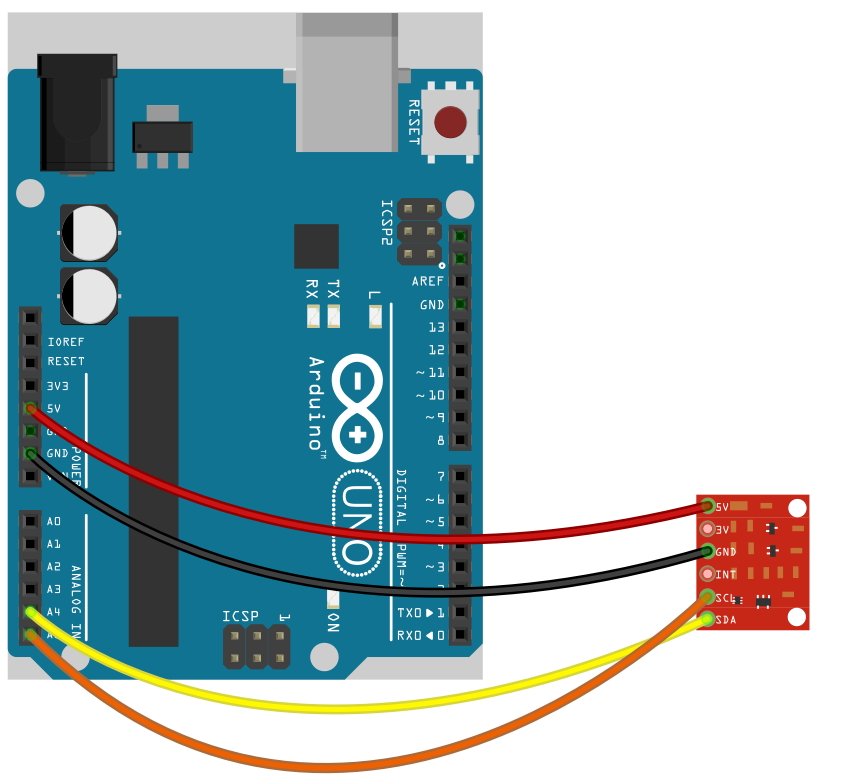
#include <Wire.h>
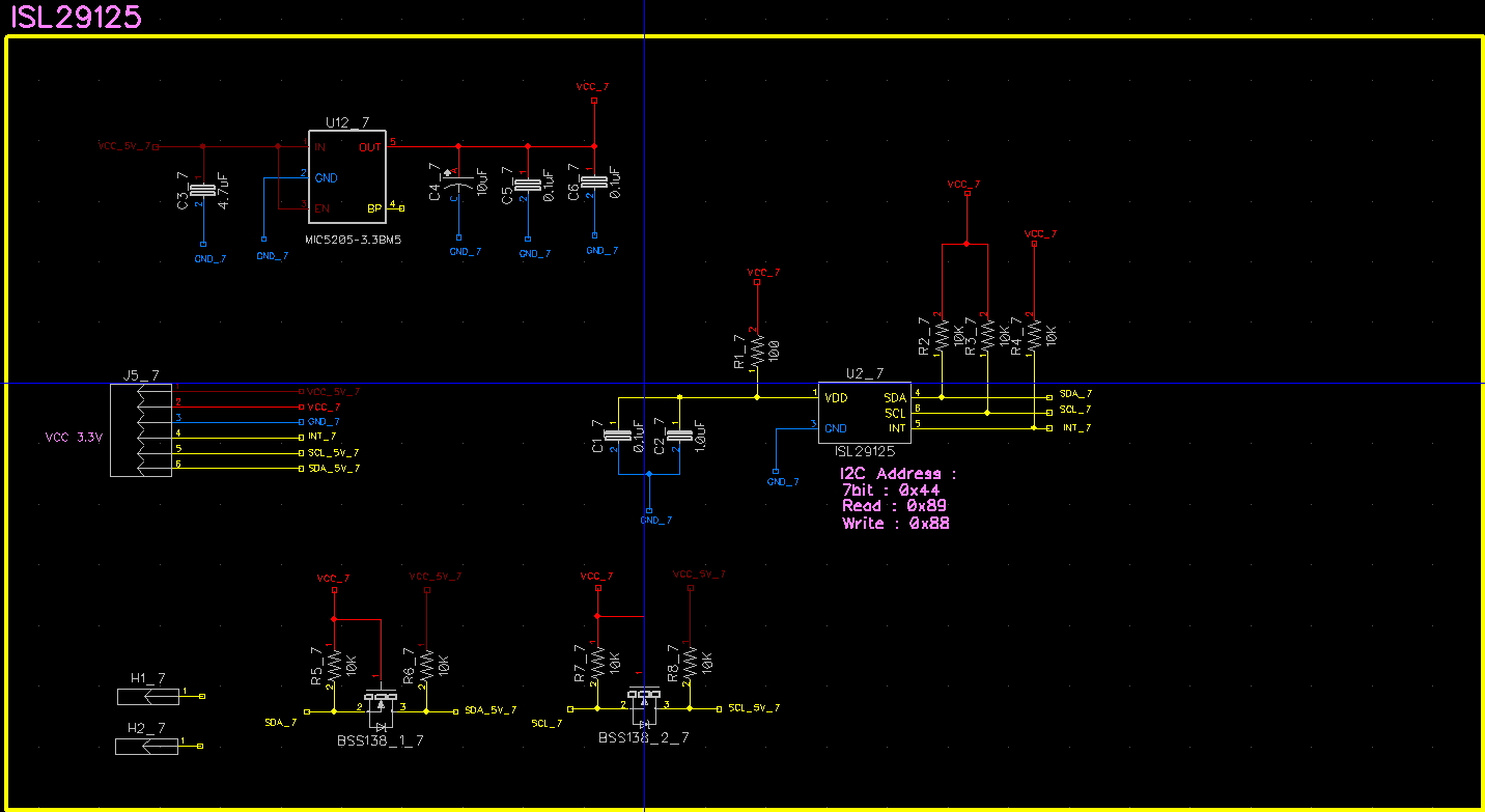
#define ISL_I2C_ADDR 0x44
/* ISL29125 Registers */
#define DEVICE_ID 0x00
#define CONFIG_1 0x01
#define CONFIG_2 0x02
#define CONFIG_3 0x03
#define THRESHOLD_LL 0x04
#define THRESHOLD_LH 0x05
#define THRESHOLD_HL 0x06
#define THRESHOLD_HH 0x07
#define STATUS 0x08
#define GREEN_L 0x09
#define GREEN_H 0x0A
#define RED_L 0x0B
#define RED_H 0x0C
#define BLUE_L 0x0D
#define BLUE_H 0x0E
/* Configuration Settings */
#define CFG_DEFAULT 0x00
/*CONFIG1
Pick a mode, determines what color[s] the sensor samples, if any */
#define CFG1_MODE_POWERDOWN 0x00
#define CFG1_MODE_G 0x01
#define CFG1_MODE_R 0x02
#define CFG1_MODE_B 0x03
#define CFG1_MODE_STANDBY 0x04
#define CFG1_MODE_RGB 0x05
#define CFG1_MODE_RG 0x06
#define CFG1_MODE_GB 0x07
/* Light intensity range
In a dark environment 375Lux is best, otherwise 10KLux is likely the best option */
#define CFG1_375LUX 0x00
#define CFG1_10KLUX 0x08
/* Change this to 12 bit if you want less accuracy, but faster sensor reads
At default 16 bit, each sensor sample for a given color is about ~100ms */
#define CFG1_16BIT 0x00
#define CFG1_12BIT 0x10
/* Unless you want the interrupt pin to be an input that triggers sensor sampling, leave this on normal */
#define CFG1_ADC_SYNC_NORMAL 0x00
#define CFG1_ADC_SYNC_TO_INT 0x20
/* CONFIG2
Selects upper or lower range of IR filtering */
#define CFG2_IR_OFFSET_OFF 0x00
#define CFG2_IR_OFFSET_ON 0x80
/* Sets amount of IR filtering, can use these presets or any value between 0x00 and 0x3F
Consult datasheet for detailed IR filtering calibration */
#define CFG2_IR_ADJUST_LOW 0x00
#define CFG2_IR_ADJUST_MID 0x20
#define CFG2_IR_ADJUST_HIGH 0x3F
// CONFIG3
// No interrupts, or interrupts based on a selected color
#define CFG3_NO_INT 0x00
#define CFG3_G_INT 0x01
#define CFG3_R_INT 0x02
#define CFG3_B_INT 0x03
// How many times a sensor sample must hit a threshold before triggering an interrupt
// More consecutive samples means more times between interrupts, but less triggers from short transients
#define CFG3_INT_PRST1 0x00
#define CFG3_INT_PRST2 0x04
#define CFG3_INT_PRST4 0x08
#define CFG3_INT_PRST8 0x0C
// If you would rather have interrupts trigger when a sensor sampling is complete, enable this
// If this is disabled, interrupts are based on comparing sensor data to threshold settings
#define CFG3_RGB_CONV_TO_INT_DISABLE 0x00
#define CFG3_RGB_CONV_TO_INT_ENABLE 0x10
// STATUS FLAG MASKS
#define FLAG_INT 0x01
#define FLAG_CONV_DONE 0x02
#define FLAG_BROWNOUT 0x04
#define FLAG_CONV_G 0x10
#define FLAG_CONV_R 0x20
#define FLAG_CONV_B 0x30
class SFE_ISL29125
{
public:
SFE_ISL29125(uint8_t addr = ISL_I2C_ADDR);
~SFE_ISL29125();
bool init();
bool reset();
bool config(uint8_t config1, uint8_t config2, uint8_t config3);
void setUpperThreshold(uint16_t data);
void setLowerThreshold(uint16_t data);
uint16_t readUpperThreshold();
uint16_t readLowerThreshold();
uint16_t readRed();
uint16_t readGreen();
uint16_t readBlue();
uint8_t readStatus();
private:
uint8_t _addr;
uint8_t read8(uint8_t reg);
void write8(uint8_t reg, uint8_t data);
uint16_t read16(uint8_t reg);
void write16(uint8_t reg, uint16_t data);
};
// Constructor - Creates sensor object and sets I2C address
SFE_ISL29125::SFE_ISL29125(uint8_t addr)
{
_addr = addr;
}
// Destructor - Deletes sensor object
SFE_ISL29125::~SFE_ISL29125()
{
}
// Initialize - returns true if successful
// Starts Wire/I2C Communication
// Verifies sensor is there by checking its device ID
// Resets all registers/configurations to factory default
// Sets configuration registers for the common use case
bool SFE_ISL29125::init()
{
bool ret = true;
uint8_t data = 0x00;
// Start I2C
Wire.begin();
// Check device ID
data = read8(DEVICE_ID);
if (data != 0x7D)
{
ret &= false;
}
// Reset registers
ret &= reset();
// Set to RGB mode, 10k lux, and high IR compensation
ret &= config(CFG1_MODE_RGB | CFG1_10KLUX, CFG2_IR_ADJUST_HIGH, CFG_DEFAULT);
return ret;
}
// Reset all registers - returns true if successful
bool SFE_ISL29125::reset()
{
uint8_t data = 0x00;
// Reset registers
write8(DEVICE_ID, 0x46);
// Check reset
data = read8(CONFIG_1);
data |= read8(CONFIG_2);
data |= read8(CONFIG_3);
data |= read8(STATUS);
if (data != 0x00)
{
return false;
}
return true;
}
// Setup Configuration registers (three registers) - returns true if successful
// Use CONFIG1 variables from SFE_ISL29125.h for first parameter config1, CONFIG2 for config2, 3 for 3
// Use CFG_DEFAULT for default configuration for that register
bool SFE_ISL29125::config(uint8_t config1, uint8_t config2, uint8_t config3)
{
bool ret = true;
uint8_t data = 0x00;
// Set 1st configuration register
write8(CONFIG_1, config1);
// Set 2nd configuration register
write8(CONFIG_2, config2);
// Set 3rd configuration register
write8(CONFIG_3, config3);
// Check if configurations were set correctly
data = read8(CONFIG_1);
if (data != config1)
{
ret &= false;
}
data = read8(CONFIG_2);
if (data != config2)
{
ret &= false;
}
data = read8(CONFIG_3);
if (data != config3)
{
ret &= false;
}
return ret;
}
// Sets upper threshold value for triggering interrupts
void SFE_ISL29125::setUpperThreshold(uint16_t data)
{
write16(THRESHOLD_HL, data);
}
// Sets lower threshold value for triggering interrupts
void SFE_ISL29125::setLowerThreshold(uint16_t data)
{
write16(THRESHOLD_LL, data);
}
// Check what the upper threshold is, 0xFFFF by default
uint16_t SFE_ISL29125::readUpperThreshold()
{
return read16(THRESHOLD_HL);
}
// Check what the upper threshold is, 0x0000 by default
uint16_t SFE_ISL29125::readLowerThreshold()
{
return read16(THRESHOLD_LL);
}
// Read the latest Sensor ADC reading for the color Red
uint16_t SFE_ISL29125::readRed()
{
return read16(RED_L);
}
// Read the latest Sensor ADC reading for the color Green
uint16_t SFE_ISL29125::readGreen()
{
return read16(GREEN_L);
}
// Read the latest Sensor ADC reading for the color Blue
uint16_t SFE_ISL29125::readBlue()
{
return read16(BLUE_L);
}
// Check status flag register that allows for checking for interrupts, brownouts, and ADC conversion completions
uint8_t SFE_ISL29125::readStatus()
{
return read8(STATUS);
}
// Generic I2C read register (single byte)
uint8_t SFE_ISL29125::read8(uint8_t reg)
{
Wire.beginTransmission(_addr);
Wire.write(reg);
Wire.endTransmission();
Wire.beginTransmission(_addr);
Wire.requestFrom(_addr,(uint8_t)1);
uint8_t data = Wire.read();
Wire.endTransmission();
return data;
}
// Generic I2C write data to register (single byte)
void SFE_ISL29125::write8(uint8_t reg, uint8_t data)
{
Wire.beginTransmission(_addr);
Wire.write(reg);
Wire.write(data);
Wire.endTransmission();
return;
}
// Generic I2C read registers (two bytes, LSB first)
uint16_t SFE_ISL29125::read16(uint8_t reg)
{
uint16_t data = 0x0000;
Wire.beginTransmission(_addr);
Wire.write(reg);
Wire.endTransmission();
Wire.beginTransmission(_addr);
Wire.requestFrom(_addr, (uint8_t)2); // request 2 bytes of data
data = Wire.read();
data |= (Wire.read() << 8);
Wire.endTransmission();
return data;
}
// Generic I2C write data to registers (two bytes, LSB first)
void SFE_ISL29125::write16(uint8_t reg, uint16_t data)
{
Wire.beginTransmission(_addr);
Wire.write(reg);
Wire.write(data);
Wire.write(data>>8);
Wire.endTransmission();
}
// Declare sensor object
SFE_ISL29125 RGB_sensor;
void setup()
{
// Initialize serial communication
Serial.begin(115200);
// Initialize the ISL29125 with simple configuration so it starts sampling
if (RGB_sensor.init())
{
Serial.println("Sensor Initialization Successful\n\r");
}
}
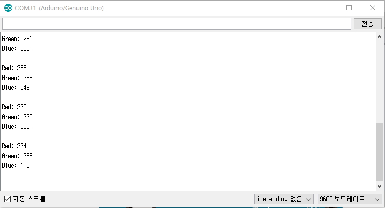
// Read sensor values for each color and print them to serial monitor
void loop()
{
// Read sensor values (16 bit integers)
unsigned int red = RGB_sensor.readRed();
unsigned int green = RGB_sensor.readGreen();
unsigned int blue = RGB_sensor.readBlue();
// Print out readings, change HEX to DEC if you prefer decimal output
Serial.print("Red: "); Serial.println(red,HEX);
Serial.print("Green: "); Serial.println(green,HEX);
Serial.print("Blue: "); Serial.println(blue,HEX);
Serial.println();
delay(2000);
}